|
RA Flexible Software Package Documentation
Release v6.5.1
|
|
|
RA Flexible Software Package Documentation
Release v6.5.1
|
|
FSP prior to v6.0.0 provided linker scripts that were common to all MCUs. Only having a single linker script per toolchain had become increasingly complex as the RA MCU family continued to grow and diversify. Starting in FSP v6.0.0, linker scripts are specific to the toolchain, MCU, and type of project being built. This means that users will need to migrate any existing linker script modifications that might have been made when migrating to FSP v6.0.0 or later.
In this guide, we will examine the methodology behind the FSP6 linker script mechanism, highlighting key areas that have changed from earlier FSP releases and providing details of how to migrate user-modified linker scripts from earlier releases to the new mechanism.
Audience: customers wishing deeper knowledge of the new linker scripting or migrating existing Renesas RA projects utilizing BSP_PLACE_IN_SECTION or custom linker scripts to the policy‑generated linker scripts.
Note: When using a Solution project it is recommended to use the Memories tab in the configuration editor to modify memory region sizes and location as necessary.
Hand‑edited linker scripts had become non‑maintainable as devices and project styles grew more complex:
Each toolchain now uses the same two‑file include pattern:
memory_regions.* – generated. Declares device/solution memory bases & lengths (e.g., FLASH/RAM/ITCM/DTCM/SDRAM/OSPI, OFS/OTP, etc.). Do not edit; update via the Solution Partitioning dialog.fsp_gen.* – generated. Defines output sections and default mappings for the current device and toolchain. Do not edit; change behavior with mapping rules.fsp.* – a tiny wrapper that INCLUDEs the two files above. This file is stable and meant to be referenced by the project.If you need custom script logic, prefer mapping rules first. If absolutely necessary, either: 1) keep a patched copy of the generated files (applied during your build before link), or 2) fork to new filenames and
INCLUDEthem fromfsp.*(works, but you disconnect from tool‑assisted mapping/partitioning).
Instead of monolithic .text/.data/.bss outputs, the new scripts split into semantically named outputs per memory and init behavior. These names are consistent across toolchains and expose Base/Limit symbols per region.
Common outputs (examples; presence depends on device/memory availability):
__flash_vectors$$ – Vector table / Reset handler__flash_readonly_gap$$ – On devices with OFS registers at 0x400, this is space before that space, where we default map content to optimize memory utilization via the DDSC linker section mapping__flash_readonly$$ – Code & const data (also GOT/EXIDX/ctor arrays: __flash_.got$$, __flash_arm.exidx$$, __flash_{preinit,init,fini}_array$$)__flash_noinit$$ – Reserved/no‑load content in flash__ram_dtc_vector$$ - The vector table for the dtc peripheral (located at start of ram for alignment restrictions)__ram_from_{ROM REGION}$$ – Initialized data copied from each available persistent source__ram_zero$$ – Zero‑initialized bss/tbss__ram_noinit$$ – Non‑initialized (e.g., heaps, main stack)__ram_tdata$$, __ram_tbss$$, __ram_thread_stack$$__ram_zero_nocache$$, __ram_noinit_nocache$$__{ROM Region}_readonly$$ - Initialized space in this region (constants, code)__{ROM Region}_noinit$$ - Uninitialized space in this region that application code can write at runtime__{RAM Region}_from_{ROM Region}$$ - Initialized data copied from each available persistent source__{RAM Region}_zero$$ – Zero‑initialized data in this region__{RAM Region}_noinit$$ – Non‑initialized data in this region__option_setting_{OFS Register}_reg$$ - Fine grained output section for each OFS registerEach output exposes ...$$Base / ...$$Limit symbols for portable startup code and diagnostics across toolchains.
Use DDSC → Linker Section Mapping
Here you can see typical default mappings for a device with the OFS flash gap.
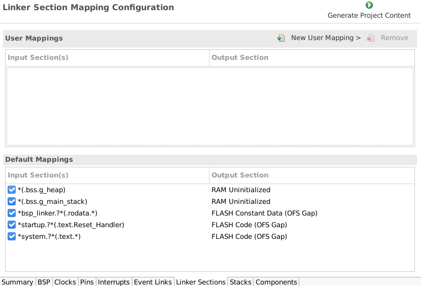
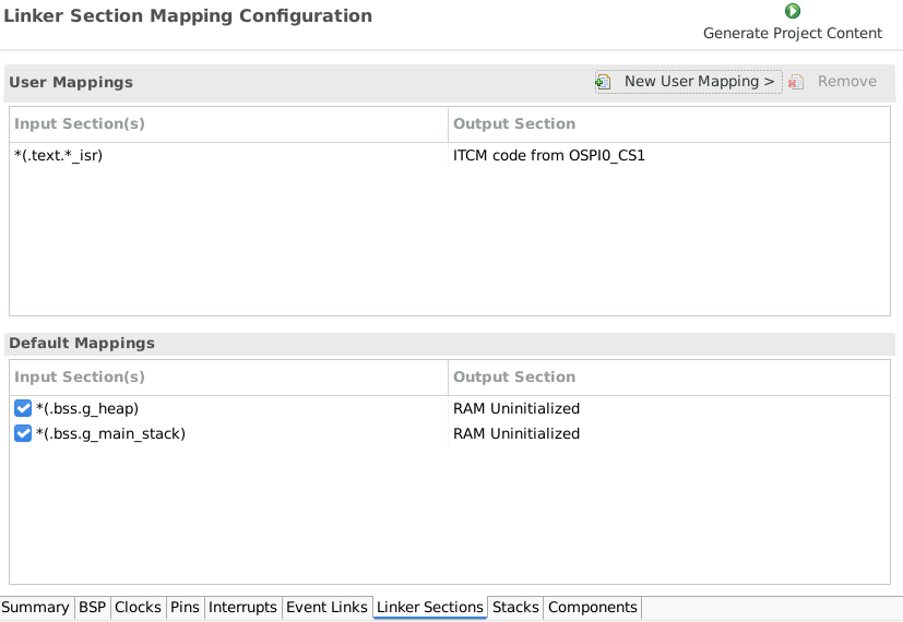
To create a new user mapping select the desired destination (and the intialization source if appropriate)
ITCM Code initialized from ITCM code from OSPI0_CS1*(.text.*_isr)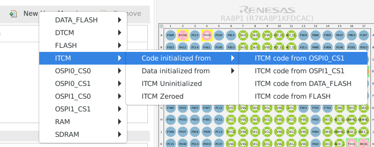
This means any function that ends in _isr will be persistently stored in OSPI0_CS1 space (in the output elf and srecord) and loaded to ITCM by the fsp startup code.
BSP_PLACE_IN_SECTION("<name>") continues to work. Some legacy section names changed for consistency; prefer mapping rules when migrating. If you keep the macro, use the input names as defined in the appendix.
Use Solution Partitioning to assign FLASH/RAM ranges across bootloader/app/TZ projects. memory_regions.* is regenerated to reflect those partitions; all scripts honor them automatically. Please refer to solution project documentation for details.
BSP_PLACE_IN_SECTION, either remove it and add a mapping rule, or rename the section to the new input names shown below.Note: In the e2 Studio tooling, dialogs related to obj-copy do not properly parse the
$$suffix, so use globbing if required (such as--remove-section=__option_setting_*)
Note: exact availability of *_from_* and *_nocache outputs depends on the device and selected memories.
fsp_gen.* and memory_regions.* are regenerated. Put customizations in mapping rules or in patches/forks.__flash_vectors$$. General code/rodata live in __flash_readonly$$ (placed after OFS flash gap where required).RAM Zero (No‑Cache)my_dma.o(.bss.my_buffer).ram_nocache__ram_zero_nocache$$ITCM Code from FLASHisr_fast.o(.text.my_isr).itcm_code_from_flash__itcm_from_flash$$OSPI_CS1 Constant Dataassets.o(.rodata*).ospi1_cs1__ospi1_cs1_readonly$$ Q: Can I still edit the scripts directly? A: You can, but we don’t recommend it. Copy to new filenames and INCLUDE them, or maintain a patch step. Otherwise, tool‑driven mapping/partitioning will be out of sync.
Q: Will old BSP_PLACE_IN_SECTION() break? A: It’s still supported. A few legacy section names changed; prefer the mapping dialog or update the section names as in the quick translation above.
Q: How do I share memory between bootloader and app? A: Use Solution Partitioning. The generator will rebuild memory_regions.* and all projects will align automatically.
Q: What about data that must not be re‑initialized? A: Use .noinit/.ram_noinit (or the mapping to RAM Non‑Initialized → __ram_noinit$$).
Q: What is the bsp_linker_info.h file located in the <configuration> folder? A: To support the seamless support of the new linker process, we must pass information to the source code (such as the source and destination of memory initializers). Unfortunately, the current DDSC tooling has limitations that only allow us to generate a header file to this location. Future releases will likely change the location of this information.
The new generator brings consistency, scalability, and zero‑touch placement across toolchains and devices. Start with Solution Partitioning and the Linker Section Mapping dialog; reserve script edits for exceptional cases via patches or forked includes.
This appendix documents the valid input linker_section values that appear in the linker script and may be referenced from user code or configuration macros.
Each section name is based on a RAM or ROM class, using a structured naming convention depending on the content type.
| RAM Class | ROM Init | Zeroed | NoInit | |||
|---|---|---|---|---|---|---|
| Code | Data | NoCache | NoCache | |||
| RAM | ✅ | ✅ | ✅ | ✅ | ✅ | ✅ |
| TCM | ✅ | ✅ | ✅ | ✅ |
| ROM Class | Code | ReadOnly | NoInit |
|---|---|---|---|
| ROM | ✅ | ✅ | ✅ |
| FLASH (Gap) | ✅ | ✅ |
These are the valid memory class identifiers used in linker_section names.
The available memory classes depend on the capabilities of your specific device. Not all devices support all RAM or ROM types.
Used for memory cleared to zero at startup.
Examples:
*(.ram)*(.sdram)*(.dtcm)Used for reserved memory (e.g., heap/stack) that doesn't require initialization at startup. The _nocache variant is only available on devices with caching hardware.
Examples:
*(.ram_noinit)*(.sdram_noinit_nocache)Used for RAM-resident code or data loaded from ROM.
Examples:
*(.ram_code_from_flash)*(.dtcm_from_data_flash)*(.tcm_code_from_qspi_flash).rom_class_code: Executable code.rom_class: Constants or read-only data.rom_class_noinit: Reserved (e.g., alignment)Examples:
*(.flash_code)*(.data_flash)*(.qspi_flash_noinit)Used only on devices with restricted flash regions (e.g., 0x400–0x43F). These sections support only code and constant data.
linker_section names follow consistent, structured patterns._nocache suffixes only for memory that must not be cached (e.g., DMA regions).