RA Flexible Software Package Documentation  Release v5.2.0

 
USB PCDC (r_usb_pcdc)

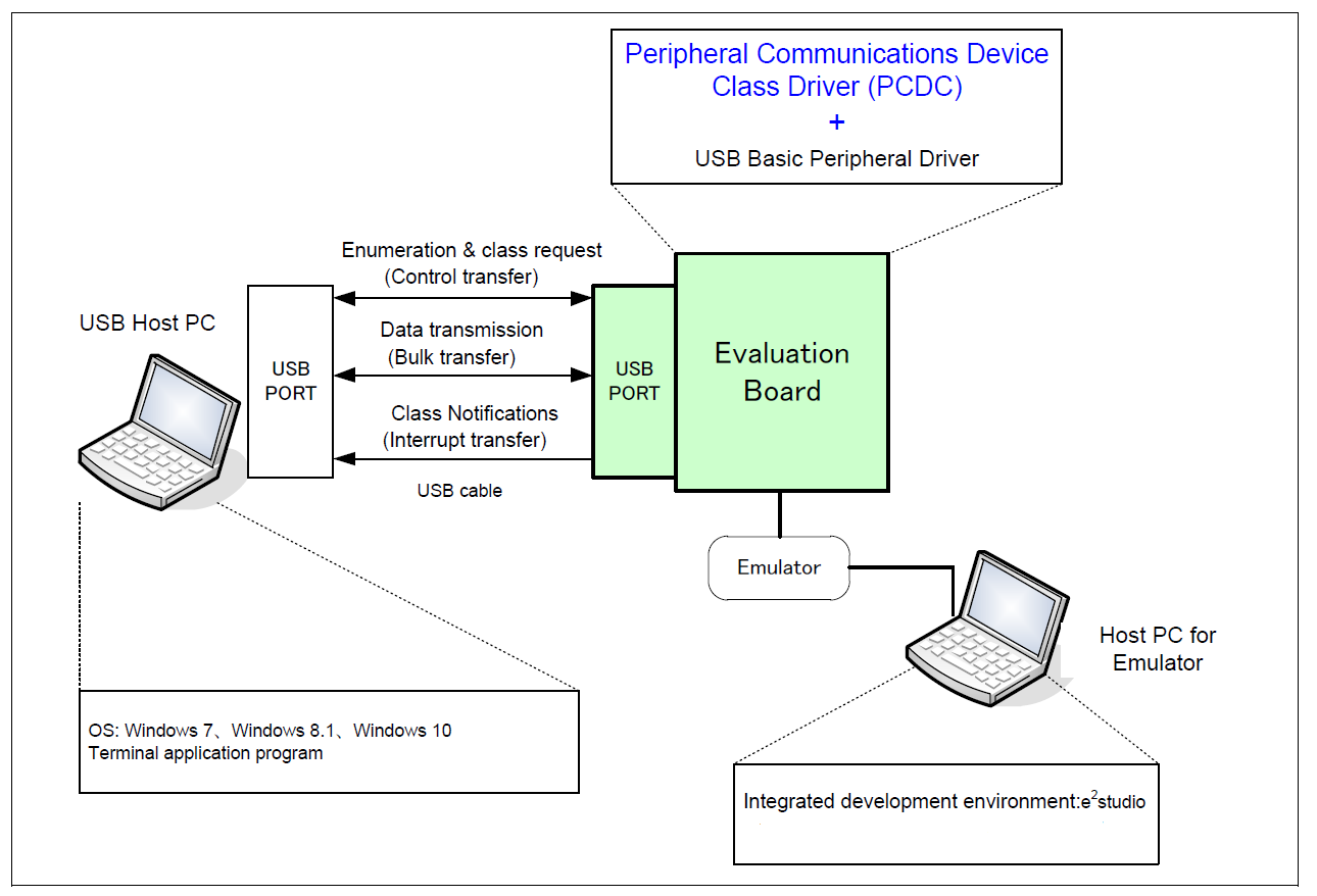
This module provides a USB Peripheral Communications Device Class Driver (PCDC). It implements the USB PCDC Interface.

Functions

Refer to USB (r_usb_basic) for the common API (r_usb_basic) to be called from the application.

Detailed Description

Overview

The r_usb_pcdc module combines with the r_usb_basic module to provide a USB Peripheral Communications Device Class (PCDC) driver. The PCDC driver conforms to Abstract Control Model of the USB Communications Device Class (CDC) specification and enables communication with a CDC host device.

Features

The r_usb_pcdc module has the following key features:

Configuration

Build Time Configurations for r_usb_pcdc

The following build time configurations are defined in fsp_cfg/r_usb_pcdc_cfg.h:

ConfigurationOptionsDefaultDescription
Bulk In Pipe
  • USB PIPE1
  • USB PIPE2
  • USB PIPE3
  • USB PIPE4
  • USB PIPE5
USB PIPE4 Select the USB pipe to use for bulk input transfers.
Bulk Out Pipe
  • USB PIPE1
  • USB PIPE2
  • USB PIPE3
  • USB PIPE4
  • USB PIPE5
USB PIPE5 Select the USB pipe to use for bulk output transfers.
Interrupt In Pipe
  • USB PIPE6
  • USB PIPE7
  • USB PIPE8
  • USB PIPE9
USB PIPE6 Select the USB pipe to use for interrupts.

Configurations for Connectivity > USB PCDC (r_usb_pcdc)

This module can be added to the Stacks tab via New Stack > Connectivity > USB PCDC (r_usb_pcdc).

ConfigurationOptionsDefaultDescription
NameName must be a valid C symbolg_pcdc0 Module name.

Note
Refer to the USB (r_usb_basic) module for hardware configuration options.

Clock Configuration

Refer to the USB (r_usb_basic) module.

Pin Configuration

Refer to the USB (r_usb_basic) module.

Usage Notes

Abstract Control Model Overview

The Abstract Control Model subclass of CDC is a technology that bridges the gap between USB devices and earlier modems (employing RS-232C connections), enabling use of application programs designed for older modems.

Class Requests (Host to Peripheral)

This driver notifies the application when receiving the following class requests:

Request Code Description
SetLineCoding 0x20 Sets communication line settings (bitrate, data length, parity, and stop bit length)
GetLineCoding 0x21 Acquires the communication line setting state
SetControlLineState 0x22 Set communication line control signals (RTS, DTR)
Note
For details concerning the Abstract Control Model requests, refer to Table 11 "Requests - Abstract Control Model" in the "USB Communications Class Subclass Specification for PSTN Devices", Revision 1.2.

Data Format of Class Requests

The data format of supported class requests is described below:

bmRequestType bRequest wValue wIndex wLength Data
0x21 SET_LINE_CODING (0x20) 0x0000 0x0000 0x0007 usb_pcdc_linecoding_t
0xA1 GET_LINE_CODING (0x21) 0x0000 0x0000 0x0007 usb_pcdc_linecoding_t
0x21 SET_CONTROL_LINE_STATE (0x22) usb_pcdc_ctrllinestate_t 0x0000 0x0000 None

Class Notifications (Peripheral to Host)

The following class notifications are supported:

Notification Code Description
SERIAL_STATE 0x20 Notification of serial line state

The data types returned are as follows:

bmRequestType bRequest wValue wIndex wLength Data
0xA1 SERIAL_STATE (0x20) 0x0000 0x0000 0x0002 usb_serial_state_bitmap_t
Note
The host is notified with SERIAL_STATE whenever a change in the UART port state is detected. This driver will automatically detect overrun, parity and framing errors. A state notification is performed when a transition from normal to error state is detected.

Virtual COM-port Usage

When connected to a PC the CDC device can be used as a virtual COM port. After enumeration, the CDC class requests GetLineCoding and SetControlLineState are executed by the target, and the CDC device is registered in Windows Device Manager as a virtual COM device.

Registering the CDC device as a virtual COM-port in Windows Device Manager enables data communication with the CDC device via a terminal app such as PuTTY. When changing settings of the serial port in the terminal application, the UART setting is propagated to the firmware via the class request SetLineCoding.

Data input (or file transmission) from the terminal app window is transmitted to the board using endpoint 2 (EP2); data from the board side is transmitted to the PC using EP1.

When the last packet of data received is the maximum packet size, and the terminal determines that there is continuous data, the received data may not be displayed in the terminal. If the received data is smaller than the maximum packet size, the data received up to that point is displayed in the terminal.

Multi Port

This driver supports simultaneous operation with Host Mass Storage Class(HMSC). If the user are using MCU that supports 2 USB modules, such as RA6M3, the user can run PCDC on one USB module and HMSC on the other. This driver does not support simultaneous operation using device classes other than HMSC.

Limitations

Examples

USB PCDC Loopback Example

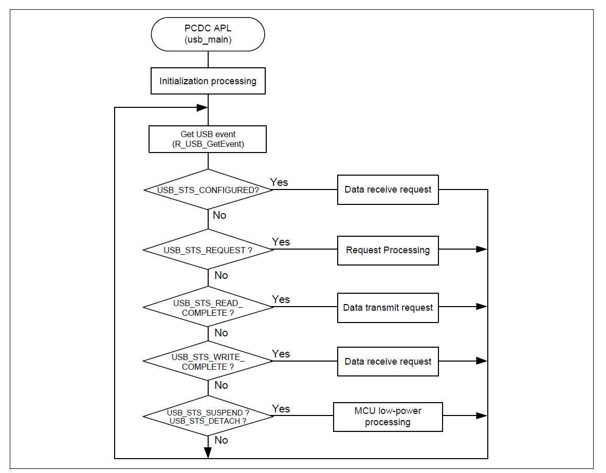
The main functions of the PCDC loopback example are as follows:

  1. Receives virtual UART configuration data from the host terminal
  2. Loops all other received data back to the host terminal
r_usb_pcdc_operating_environment_echo.png
Example Operating Environment
r_usb_pcdc_task_flow_sample.png
Main Loop processing (Echo mode)
#define USB_APL_YES (1U)
#define USB_APL_NO (0U)
#define APL_NUM_USB_EVENT (10U)
// #define APL_USE_BAREMETAL_CALLBACK USB_APL_NO
#define APL_USE_BAREMETAL_CALLBACK USB_APL_YES
/******************************************************************************
* Private global variables and functions
******************************************************************************/
extern const usb_cfg_t g_basic0_cfg;
static uint8_t g_buf[DATA_LEN];
static usb_pcdc_linecoding_t g_line_coding;
extern uint8_t g_apl_device[];
extern uint8_t g_apl_configuration[];
extern uint8_t g_apl_hs_configuration[];
extern uint8_t g_apl_qualifier_descriptor[];
extern uint8_t * g_apl_string_table[];
usb_instance_ctrl_t g_basic0_ctrl;
#if (BSP_CFG_RTOS == 2)
QueueHandle_t g_apl_mbx_hdl;
#endif /* (BSP_CFG_RTOS == 2) */
#if (BSP_CFG_RTOS == 0) && (APL_USE_BAREMETAL_CALLBACK == USB_YES)
usb_callback_args_t g_apl_usb_event;
usb_callback_args_t g_apl_usb_event_buf[APL_NUM_USB_EVENT];
uint8_t g_apl_usb_event_wp = 0;
uint8_t g_apl_usb_event_rp = 0;
#endif /* (BSP_CFG_RTOS == 0) && (APL_USE_BAREMETAL_CALLBACK == USB_YES) */
/******************************************************************************
* Exported global functions (to be accessed by other files)
******************************************************************************/
void usb_pcdc_example(void);
#if (BSP_CFG_RTOS == 0) && (APL_USE_BAREMETAL_CALLBACK == USB_YES)
void usb_apl_callback(usb_callback_args_t * p_event);
#endif
#if (BSP_CFG_RTOS == 2)
void usb_apl_callback(usb_event_info_t * p_api_event, usb_hdl_t cur_task, usb_onoff_t usb_state);
#endif
/******************************************************************************
* Renesas Peripheral Communications Devices Class Sample Code functions
******************************************************************************/
#if (BSP_CFG_RTOS == 2)
/******************************************************************************
* Function Name : usb_apl_callback
* Description : Callback function for Application program
* Arguments : usb_event_info_t *p_api_event : Control structure for USB API.
* : usb_hdl_t cur_task : Task Handle
* : uint8_t usb_state : USB_ON(USB_STATUS_REQUEST) / USB_OFF
* Return value : none
******************************************************************************/
void usb_apl_callback (usb_event_info_t * p_api_event, usb_hdl_t cur_task, usb_onoff_t usb_state)
{
(void) usb_state;
(void) cur_task;
xQueueSend(g_apl_mbx_hdl, (const void *) &p_api_event, (TickType_t) (0));
} /* End of function usb_apl_callback */
#endif /* (BSP_CFG_RTOS == 2) */
/******************************************************************************
* Function Name : usb_apl_callback
* Description : Callback function for Application program
* Arguments : usb_callback_args_t * p_event : Pointer to usb_callback_args_t structure
* Return value : none
******************************************************************************/
#if (BSP_CFG_RTOS == 0) && (APL_USE_BAREMETAL_CALLBACK == USB_YES)
void usb_apl_callback (usb_callback_args_t * p_event)
{
g_apl_usb_event_buf[g_apl_usb_event_wp] = *p_event;
g_apl_usb_event_wp++;
g_apl_usb_event_wp %= APL_NUM_USB_EVENT;
}
#endif /* (BSP_CFG_RTOS == 0) && (APL_USE_BAREMETAL_CALLBACK == USB_YES) */
/******************************************************************************
* Function Name : usb_pcdc_example
* Description : Peripheral CDC application main process
* Arguments : none
* Return value : none
******************************************************************************/
void usb_pcdc_example (void)
{
usb_event_info_t event_info;
#if (BSP_CFG_RTOS == 2)
usb_event_info_t * p_mess;
#endif
g_usb_on_usb.open(&g_basic0_ctrl, &g_basic0_cfg);
#if (BSP_CFG_RTOS == 0) && (APL_USE_BAREMETAL_CALLBACK == USB_YES)
g_usb_on_usb.callbackMemorySet(&g_basic0_ctrl, &g_apl_usb_event);
#endif /* (APL_USE_BAREMETAL_CALLBACK == USB_YES) */
while (1)
{
#if (BSP_CFG_RTOS == 2) /* FreeRTOS */
xQueueReceive(g_apl_mbx_hdl, (void *) &p_mess, portMAX_DELAY);
event_info = *p_mess;
event = event_info.event;
#else /* (BSP_CFG_RTOS == 2) */
#if (APL_USE_BAREMETAL_CALLBACK == USB_YES)
g_usb_on_usb.driverActivate(&g_basic0_ctrl);
if (g_apl_usb_event_wp != g_apl_usb_event_rp)
{
event_info = g_apl_usb_event_buf[g_apl_usb_event_rp];
g_apl_usb_event_rp++;
g_apl_usb_event_rp %= APL_NUM_USB_EVENT;
event = event_info.event;
}
#else /* (APL_USE_BAREMETAL_CALLBACK == USB_YES) */
/* Get USB event data */
g_usb_on_usb.eventGet(&event_info, &event);
#endif
#endif /* (BSP_CFG_RTOS == 2) */
/* Handle the received event (if any) */
switch (event)
{
/* Initialization complete; get data from host */
g_usb_on_usb.read(&g_basic0_ctrl, g_buf, DATA_LEN, USB_CLASS_PCDC);
break;
/* Loop back received data to host */
g_usb_on_usb.write(&g_basic0_ctrl, g_buf, event_info.data_size, USB_CLASS_PCDC);
break;
case USB_STATUS_REQUEST: /* Receive Class Request */
if (USB_PCDC_SET_LINE_CODING == (event_info.setup.request_type & USB_BREQUEST))
{
/* Configure virtual UART settings */
g_usb_on_usb.periControlDataGet(&g_basic0_ctrl, (uint8_t *) &g_line_coding, LINE_CODING_LENGTH);
}
else if (USB_PCDC_GET_LINE_CODING == (event_info.setup.request_type & USB_BREQUEST))
{
/* Send virtual UART settings back to host */
g_usb_on_usb.periControlDataSet(&g_basic0_ctrl, (uint8_t *) &g_line_coding, LINE_CODING_LENGTH);
}
else
{
/* ACK all other status requests */
g_usb_on_usb.periControlStatusSet(&g_basic0_ctrl, USB_SETUP_STATUS_ACK);
}
break;
break;
default:
break;
}
}
} /* End of function usb_pcdc_example() */

Descriptor

A template for PCDC descriptors can be found in ra/fsp/src/r_usb_pcdc/r_usb_pcdc_descriptor.c.template. Also, please be sure to use your vendor ID.