|
RA Flexible Software Package Documentation
Release v6.5.1
|
|
|
RA Flexible Software Package Documentation
Release v6.5.1
|
|
Functions | |
| fsp_err_t | R_CANFD_Open (can_ctrl_t *const p_api_ctrl, can_cfg_t const *const p_cfg) |
| fsp_err_t | R_CANFD_Close (can_ctrl_t *const p_api_ctrl) |
| fsp_err_t | R_CANFD_Write (can_ctrl_t *const p_api_ctrl, uint32_t buffer, can_frame_t *const p_frame) |
| fsp_err_t | R_CANFD_Read (can_ctrl_t *const p_api_ctrl, uint32_t buffer, can_frame_t *const p_frame) |
| fsp_err_t | R_CANFD_ModeTransition (can_ctrl_t *const p_api_ctrl, can_operation_mode_t operation_mode, can_test_mode_t test_mode) |
| fsp_err_t | R_CANFD_InfoGet (can_ctrl_t *const p_api_ctrl, can_info_t *const p_info) |
| fsp_err_t | R_CANFD_CallbackSet (can_ctrl_t *const p_api_ctrl, void(*p_callback)(can_callback_args_t *), void *const p_context, can_callback_args_t *const p_callback_memory) |
Driver for the CANFD peripheral on RA MCUs. This module implements the CAN Interface.
The CANFD module can be used to communicate over CAN networks, optionally using Flexible Data (CAN-FD) to accelerate the data phase. A variety of message filtering and buffer options are available. This document covers both the CANFD (r_canfd) and CANFD Lite (r_canfdlite) modules as they are based on the same hardware.
| RA6M5 | RA6T2 | RA8M1 | |
|---|---|---|---|
| Channels | 2 | 1 | 2 |
| Max nominal bitrate | 1 Mbps | 1 Mbps | 1 Mbps |
| Max data bitrate | 5 Mbps | 5 Mbps | 8 Mbps |
| Filter rules | 128 | 32 | 16/ch |
| TX message buffers | 16/ch | 4 | 4/ch |
| RX message buffers | 32 | 32 | 16/ch |
| RX FIFOs | 8 | 2 | 2/ch |
| RX Buffer RAM | 4864 bytes | 1216 bytes | 1216 bytes |
| Common FIFOs | 3/ch | 1 | 1/ch |
| RA6M5 | RA6T2 | RA8M1 | |
|---|---|---|---|
| Max 64-byte storage | 64 messages | 16 messages | 16 messages |
| Max 8-byte storage | 243 messages | 60 messages | 60 messages |
| RA6M5 | RA6T2 | RA8M1 | |
|---|---|---|---|
| Maximum payload size | 64 bytes | 64 bytes | 64 bytes |
| Maximum FIFO depth | 128 messages | 48 messages | 48 messages |
| Device Group | Devices |
|---|---|
| RA4 | RA4C1, RA4E2, RA4L1, RA4T1 |
| RA6 | RA6E2, RA6M5, RA6T2, RA6T3 |
| RA8 | RA8D1, RA8D2, RA8E1, RA8E2, RA8M1, RA8M2, RA8P1, RA8T1, RA8T2 |
| Configuration | Options | Default | Description |
|---|---|---|---|
| Global Error Interrupt | |||
| Callback Channel | MCU Specific Options | Specify which channel callback should be called to handle global errors. When starting the driver this channel must be opened first. | |
| Priority | MCU Specific Options | This interrupt is fired for each of the error sources selected below. | |
| Sources |
| 0U | Select which errors should trigger an interrupt. |
| Reception | |||
| Reception > FIFOs | |||
| Reception > FIFOs > FIFO 0 | |||
| Enable |
| Enabled | Enable or disable RX FIFO 0. |
| Interrupt Mode | MCU Specific Options | Set the interrupt mode for RX FIFO 0. Threshold mode will only fire an interrupt each time an incoming message crosses the threshold value set below. | |
| Interrupt Threshold | MCU Specific Options | Set the interrupt threshold value for RX FIFO 0. This setting is only applicable when the Interrupt Mode is set to 'At Threshold Value'. | |
| Payload Size | MCU Specific Options | Select the message payload size for RX FIFO 0. | |
| Depth | MCU Specific Options | Select the number of stages for RX FIFO 0. | |
| Reception > FIFOs > FIFO 1 | |||
| Enable |
| Disabled | Enable or disable RX FIFO 1. |
| Interrupt Mode | MCU Specific Options | Set the interrupt mode for RX FIFO 1. Threshold mode will only fire an interrupt each time an incoming message crosses the threshold value set below. | |
| Interrupt Threshold | MCU Specific Options | Set the interrupt threshold value for RX FIFO 1. This setting is only applicable when the Interrupt Mode is set to 'At Threshold Value'. | |
| Payload Size | MCU Specific Options | Select the message payload size for RX FIFO 1. | |
| Depth | MCU Specific Options | Select the number of stages for RX FIFO 1. | |
| Reception > FIFOs > FIFO 2 | |||
| Enable |
| Disabled | Enable or disable RX FIFO 2. |
| Interrupt Mode | MCU Specific Options | Set the interrupt mode for RX FIFO 2. Threshold mode will only fire an interrupt each time an incoming message crosses the threshold value set below. | |
| Interrupt Threshold | MCU Specific Options | Set the interrupt threshold value for RX FIFO 2. This setting is only applicable when the Interrupt Mode is set to 'At Threshold Value'. | |
| Payload Size | MCU Specific Options | Select the message payload size for RX FIFO 2. | |
| Depth | MCU Specific Options | Select the number of stages for RX FIFO 2. | |
| Reception > FIFOs > FIFO 3 | |||
| Enable |
| Disabled | Enable or disable RX FIFO 3. |
| Interrupt Mode | MCU Specific Options | Set the interrupt mode for RX FIFO 3. Threshold mode will only fire an interrupt each time an incoming message crosses the threshold value set below. | |
| Interrupt Threshold | MCU Specific Options | Set the interrupt threshold value for RX FIFO 3. This setting is only applicable when the Interrupt Mode is set to 'At Threshold Value'. | |
| Payload Size | MCU Specific Options | Select the message payload size for RX FIFO 3. | |
| Depth | MCU Specific Options | Select the number of stages for RX FIFO 3. | |
| Reception > FIFOs > FIFO 4 | |||
| Enable |
| Disabled | Enable or disable RX FIFO 4. |
| Interrupt Mode | MCU Specific Options | Set the interrupt mode for RX FIFO 4. Threshold mode will only fire an interrupt each time an incoming message crosses the threshold value set below. | |
| Interrupt Threshold | MCU Specific Options | Set the interrupt threshold value for RX FIFO 4. This setting is only applicable when the Interrupt Mode is set to 'At Threshold Value'. | |
| Payload Size | MCU Specific Options | Select the message payload size for RX FIFO 4. | |
| Depth | MCU Specific Options | Select the number of stages for RX FIFO 4. | |
| Reception > FIFOs > FIFO 5 | |||
| Enable |
| Disabled | Enable or disable RX FIFO 5. |
| Interrupt Mode | MCU Specific Options | Set the interrupt mode for RX FIFO 5. Threshold mode will only fire an interrupt each time an incoming message crosses the threshold value set below. | |
| Interrupt Threshold | MCU Specific Options | Set the interrupt threshold value for RX FIFO 5. This setting is only applicable when the Interrupt Mode is set to 'At Threshold Value'. | |
| Payload Size | MCU Specific Options | Select the message payload size for RX FIFO 5. | |
| Depth | MCU Specific Options | Select the number of stages for RX FIFO 5. | |
| Reception > FIFOs > FIFO 6 | |||
| Enable |
| Disabled | Enable or disable RX FIFO 6. |
| Interrupt Mode | MCU Specific Options | Set the interrupt mode for RX FIFO 6. Threshold mode will only fire an interrupt each time an incoming message crosses the threshold value set below. | |
| Interrupt Threshold | MCU Specific Options | Set the interrupt threshold value for RX FIFO 6. This setting is only applicable when the Interrupt Mode is set to 'At Threshold Value'. | |
| Payload Size | MCU Specific Options | Select the message payload size for RX FIFO 6. | |
| Depth | MCU Specific Options | Select the number of stages for RX FIFO 6. | |
| Reception > FIFOs > FIFO 7 | |||
| Enable |
| Disabled | Enable or disable RX FIFO 7. |
| Interrupt Mode | MCU Specific Options | Set the interrupt mode for RX FIFO 7. Threshold mode will only fire an interrupt each time an incoming message crosses the threshold value set below. | |
| Interrupt Threshold | MCU Specific Options | Set the interrupt threshold value for RX FIFO 7. This setting is only applicable when the Interrupt Mode is set to 'At Threshold Value'. | |
| Payload Size | MCU Specific Options | Select the message payload size for RX FIFO 7. | |
| Depth | MCU Specific Options | Select the number of stages for RX FIFO 7. | |
| Interrupt Priority | MCU Specific Options | This priority level will apply to all FIFO interrupts globally. | |
| Reception > Message Buffers | |||
| Number of Buffers | RX Message Buffer number must be an integer between 0 and 32. | 0 | Number of message buffers available for reception. As there is no interrupt for message buffer reception it is recommended to use RX FIFOs instead. Set this value to 0 to disable RX Message Buffers. |
| Payload Size |
| 8 bytes | Payload size for all RX Message Buffers. |
| Reception > Acceptance Filtering | |||
| Channel 0 Rule Count | The number of AFL rules must be a positive integer. | 32 | Number of acceptance filter list rules dedicated to Channel 0. |
| Channel 1 Rule Count | The number of AFL rules must be a positive integer. | 0 | Number of acceptance filter list rules dedicated to Channel 1. |
| Flexible Data (FD) | |||
| Protocol Exceptions |
| Enabled (ISO 11898-1) | Select whether to enter the protocol exception handling state when a RES bit is sampled recessive as defined in ISO 11898-1. |
| Payload Overflow |
| Reject | Configure whether received messages larger than the destination buffer should be truncated or rejected. |
| Common FIFOs | |||
| Common FIFOs > FIFO 0 | |||
| Enable |
| Disabled | Enable or disable Common FIFO 0. |
| Mode |
| Receive | Select the operation mode for Common FIFO 0. |
| RX Interrupt Enable |
| Disabled | Enable to allow interrupts on message receiption for Common FIFO 0. |
| TX Interrupt Enable |
| Disabled | Enable to allow interrupts on message transmission for Common FIFO 0. |
| Interrupt Mode |
| Threshold | Set the interrupt mode for Common FIFO 0. Threshold mode will only fire an interrupt each time an incoming message crosses the threshold value set below or when all messages have been transmitted. |
| Interrupt Threshold | MCU Specific Options | Set the interrupt threshold value for Common FIFO 0. This setting is only applicable when the Interrupt Mode is set to 'At Threshold Value'. | |
| Payload Size | MCU Specific Options | Select the message payload size for Common FIFO 0. | |
| Depth | MCU Specific Options | Select the number of stages for Common FIFO 0. | |
| TX Message Buffer | MCU Specific Options | Select the TX message buffer that participates in TX scans related to Common FIFO 0. | |
| Interval TX Delay | TX delay must be an integer between 0 and 255. | 0 | Selects the delay between successive transmission for Common FIFO 0 in units of the Interval Timer Clock. |
| Interval Timer |
| Reference clock | Select the source of the interval timer clock for Common FIFO 0. The reference clock can be scaled by x10 below. |
| Interval Timer Reference Clock Resolution |
| x1 | Selects the timer resolution if the reference clock is selected as the timer source for Common FIFO 0. |
| Common FIFOs > FIFO 1 | |||
| Enable |
| Disabled | Enable or disable Common FIFO 1. |
| Mode |
| Receive | Select the operation mode for Common FIFO 1. |
| RX Interrupt Enable |
| Disabled | Enable to allow interrupts on message receiption for Common FIFO 1. |
| TX Interrupt Enable |
| Disabled | Enable to allow interrupts on message transmission for Common FIFO 1. |
| Interrupt Mode |
| Threshold | Set the interrupt mode for Common FIFO 1. Threshold mode will only fire an interrupt each time an incoming message crosses the threshold value set below or when all messages have been transmitted. |
| Interrupt Threshold | MCU Specific Options | Set the interrupt threshold value for Common FIFO 1. This setting is only applicable when the Interrupt Mode is set to 'At Threshold Value'. | |
| Payload Size | MCU Specific Options | Select the message payload size for Common FIFO 1. | |
| Depth | MCU Specific Options | Select the number of stages for Common FIFO 1. | |
| TX Message Buffer | MCU Specific Options | Select the TX message buffer that participates in TX scans related to Common FIFO 1. | |
| Interval TX Delay | TX delay must be an integer between 0 and 255. | 0 | Selects the delay between successive transmission for Common FIFO 1 in units of the Interval Timer Clock. |
| Interval Timer |
| Reference clock | Select the source of the interval timer clock for Common FIFO 1. The reference clock can be scaled by x10 below. |
| Interval Timer Reference Clock Resolution |
| x1 | Selects the timer resolution if the reference clock is selected as the timer source for Common FIFO 1. |
| Common FIFOs > FIFO 2 | |||
| Enable |
| Disabled | Enable or disable Common FIFO 2. |
| Mode |
| Receive | Select the operation mode for Common FIFO 2. |
| RX Interrupt Enable |
| Disabled | Enable to allow interrupts on message receiption for Common FIFO 2. |
| TX Interrupt Enable |
| Disabled | Enable to allow interrupts on message transmission for Common FIFO 2. |
| Interrupt Mode |
| Threshold | Set the interrupt mode for Common FIFO 2. Threshold mode will only fire an interrupt each time an incoming message crosses the threshold value set below or when all messages have been transmitted. |
| Interrupt Threshold | MCU Specific Options | Set the interrupt threshold value for Common FIFO 2. This setting is only applicable when the Interrupt Mode is set to 'At Threshold Value'. | |
| Payload Size | MCU Specific Options | Select the message payload size for Common FIFO 2. | |
| Depth | MCU Specific Options | Select the number of stages for Common FIFO 2. | |
| TX Message Buffer | MCU Specific Options | Select the TX message buffer that participates in TX scans related to Common FIFO 2. | |
| Interval TX Delay | TX delay must be an integer between 0 and 255. | 0 | Selects the delay between successive transmission for Common FIFO 2 in units of the Interval Timer Clock. |
| Interval Timer |
| Reference clock | Select the source of the interval timer clock for Common FIFO 2. The reference clock can be scaled by x10 below. |
| Interval Timer Reference Clock Resolution |
| x1 | Selects the timer resolution if the reference clock is selected as the timer source for Common FIFO 2. |
| Common FIFOs > FIFO 3 | |||
| Enable |
| Disabled | Enable or disable Common FIFO 3. |
| Mode |
| Receive | Select the operation mode for Common FIFO 3. |
| RX Interrupt Enable |
| Disabled | Enable to allow interrupts on message receiption for Common FIFO 3. |
| TX Interrupt Enable |
| Disabled | Enable to allow interrupts on message transmission for Common FIFO 3. |
| Interrupt Mode |
| Threshold | Set the interrupt mode for Common FIFO 3. Threshold mode will only fire an interrupt each time an incoming message crosses the threshold value set below or when all messages have been transmitted. |
| Interrupt Threshold | MCU Specific Options | Set the interrupt threshold value for Common FIFO 3. This setting is only applicable when the Interrupt Mode is set to 'At Threshold Value'. | |
| Payload Size | MCU Specific Options | Select the message payload size for Common FIFO 3. | |
| Depth | MCU Specific Options | Select the number of stages for Common FIFO 3. | |
| TX Message Buffer | MCU Specific Options | Select the TX message buffer that participates in TX scans related to Common FIFO 3. | |
| Interval TX Delay | TX delay must be an integer between 0 and 255. | 0 | Selects the delay between successive transmission for Common FIFO 3 in units of the Interval Timer Clock. |
| Interval Timer |
| Reference clock | Select the source of the interval timer clock for Common FIFO 3. The reference clock can be scaled by x10 below. |
| Interval Timer Reference Clock Resolution |
| x1 | Selects the timer resolution if the reference clock is selected as the timer source for Common FIFO 3. |
| Common FIFOs > FIFO 4 | |||
| Enable |
| Disabled | Enable or disable Common FIFO 4. |
| Mode |
| Receive | Select the operation mode for Common FIFO 4. |
| RX Interrupt Enable |
| Disabled | Enable to allow interrupts on message receiption for Common FIFO 4. |
| TX Interrupt Enable |
| Disabled | Enable to allow interrupts on message transmission for Common FIFO 4. |
| Interrupt Mode |
| Threshold | Set the interrupt mode for Common FIFO 4. Threshold mode will only fire an interrupt each time an incoming message crosses the threshold value set below or when all messages have been transmitted. |
| Interrupt Threshold | MCU Specific Options | Set the interrupt threshold value for Common FIFO 4. This setting is only applicable when the Interrupt Mode is set to 'At Threshold Value'. | |
| Payload Size | MCU Specific Options | Select the message payload size for Common FIFO 4. | |
| Depth | MCU Specific Options | Select the number of stages for Common FIFO 4. | |
| TX Message Buffer | MCU Specific Options | Select the TX message buffer that participates in TX scans related to Common FIFO 4. | |
| Interval TX Delay | TX delay must be an integer between 0 and 255. | 0 | Selects the delay between successive transmission for Common FIFO 4 in units of the Interval Timer Clock. |
| Interval Timer |
| Reference clock | Select the source of the interval timer clock for Common FIFO 4. The reference clock can be scaled by x10 below. |
| Interval Timer Reference Clock Resolution |
| x1 | Selects the timer resolution if the reference clock is selected as the timer source for Common FIFO 4. |
| Common FIFOs > FIFO 5 | |||
| Enable |
| Disabled | Enable or disable Common FIFO 5. |
| Mode |
| Receive | Select the operation mode for Common FIFO 5. |
| RX Interrupt Enable |
| Disabled | Enable to allow interrupts on message receiption for Common FIFO 5. |
| TX Interrupt Enable |
| Disabled | Enable to allow interrupts on message transmission for Common FIFO 5. |
| Interrupt Mode |
| Threshold | Set the interrupt mode for Common FIFO 5. Threshold mode will only fire an interrupt each time an incoming message crosses the threshold value set below or when all messages have been transmitted. |
| Interrupt Threshold | MCU Specific Options | Set the interrupt threshold value for Common FIFO 5. This setting is only applicable when the Interrupt Mode is set to 'At Threshold Value'. | |
| Payload Size | MCU Specific Options | Select the message payload size for Common FIFO 5. | |
| Depth | MCU Specific Options | Select the number of stages for Common FIFO 5. | |
| TX Message Buffer | MCU Specific Options | Select the TX message buffer that participates in TX scans related to Common FIFO 5. | |
| Interval TX Delay | TX delay must be an integer between 0 and 255. | 0 | Selects the delay between successive transmission for Common FIFO 5 in units of the Interval Timer Clock. |
| Interval Timer |
| Reference clock | Select the source of the interval timer clock for Common FIFO 5. The reference clock can be scaled by x10 below. |
| Interval Timer Reference Clock Resolution |
| x1 | Selects the timer resolution if the reference clock is selected as the timer source for Common FIFO 5. |
| Parameter Checking |
| Default (BSP) | If selected code for parameter checking is included in the build. |
| Transmission Priority |
| Buffer Number | Select how messages should be prioritized for transmission. In either case, lower numbers indicate higher priority. |
| DLC Check |
| config.driver.canfd.dlc_check.disabled | When enabled received messages will be rejected if their DLC field is less than the value configured in the associated AFL rule. If 'Enabled w/truncate' is selected and a message passes the DLC check the DLC field is set to the value in the associated AFL rule and any excess data is discarded. |
| Interval Timer Prescaler | Timer prescaler must be an integer between 0 and 65535. | 0 | FIFO interval timer prescaler, required for Interval TX Delay. |
| Configuration | Options | Default | Description |
|---|---|---|---|
| General | |||
| Name | Name must be a valid C symbol | g_canfd0 | Module name. |
| Channel | Channel should be 0 or 1 | 0 | Specify the CAN channel to use. |
| Bitrate | |||
| Bitrate > Automatic | |||
| Nominal Rate (bps) | Must be a valid integer with a maximum of 1MHz. | 500000 | Specify nominal bitrate in bits per second. |
| FD Data Rate (bps) | Must be a valid integer | 2000000 | Specify data bitrate in bits per second. This value is not used when sending messages without the FD and BRS bits enabled and should be left at the default setting if only Classical CAN will be used. |
| Sample Point (%) | Must be a valid integer between 60 and 99. | 75 | Specify desired sample point. |
| Bitrate > Manual | |||
| Bitrate > Manual > Nominal | |||
| Prescaler (divisor) | Value must be a non-negative integer between 1 and 1024. | 1 | Specify clock divisor for nominal bitrate. |
| Time Segment 1 (Tq) | Value must be a non-negative integer between 2 and 256. | 29 | Select the Time Segment 1 value. Check module usage notes for how to calculate this value. |
| Time Segment 2 (Tq) | Value must be a non-negative integer between 2 and 128. | 10 | Select the Time Segment 2 value. Check module usage notes for how to calculate this value. |
| Sync Jump Width (Tq) | Value must be a non-negative integer between 1 and 128. | 4 | Select the Synchronization Jump Width value. Check module usage notes for how to calculate this value. |
| Bitrate > Manual > Data | |||
| Prescaler (divisor) | Value must be a non-negative integer between 1 and 256. | 1 | Specify clock divisor for data bitrate. |
| Time Segment 1 (Tq) | Value must be a non-negative integer between 2 and 32. | 5 | Select the Time Segment 1 value. Check module usage notes for how to calculate this value. |
| Time Segment 2 (Tq) | Value must be a non-negative integer between 2 and 16. | 2 | Select the Time Segment 2 value. Check module usage notes for how to calculate this value. |
| Sync Jump Width (Tq) | Value must be a non-negative integer between 1 and 16. | 1 | Select the Synchronization Jump Width value. Check module usage notes for how to calculate this value. |
| Use manual settings |
| No | Select whether or not to override automatic baudrate generation and instead use the values specified here. |
| Delay Compensation |
| Enable | When enabled the CANFD module will automatically compensate for any transceiver or bus delay between transmitted and received bits. When manually supplying bit timing values with delay compensation enabled be sure the data prescaler is 2 or smaller for correct operation. |
| Interrupts | |||
| Callback | Name must be a valid C symbol | canfd0_callback | A user callback function. If this callback function is provided, it is called from the interrupt service routine (ISR) each time any interrupt occurs. |
| Channel Interrupt Priority Level | MCU Specific Options | Channel Error/Transmit interrupt priority. | |
| Transmit Interrupts | MCU Specific Options | Select which TX Message Buffers should trigger an interrupt when transmission is complete. | |
| Channel Error Interrupts |
| 0U | Select which channel error interrupt sources to enable. |
| Filter List Array | Name must be a valid C symbol | p_canfd0_afl | Acceptance Filter List (AFL) rule array symbol name. |
The CANFD peripheral uses PLL or PLL2 as its clock source. The RA Configuration editor will attempt to get as close as possible to the supplied bitrate with the configured clock source. To achieve an exact bitrate the CANFD source clock or divisor may need to be adjusted to meet the criteria in the formula below:
For CANFD, the possible values for each element are as follows:
| Element | Min | Max (Nominal) | Max (Data) |
|---|---|---|---|
| Bitrate | - | 1 Mbps | 5-8 Mbps* |
| Time Segment 1 | 2 Tq | 256 Tq | 32 Tq |
| Time Segment 2 | 2 Tq | 128 Tq | 16 Tq |
| Sync Jump Width | 1 Tq | Time Segment 2 | Time Segment 2 |
| Prescalar | 1 | 1024 | 256 |
Use the Clocks tab of the RA Configuration editor to configure the CANFD clock source/divisor as well as to set the frequency of PLL or PLL2. To change the clock frequency at run-time, use the CGC Interface. Refer to the CGC module guide for more information on configuring clocks.
CANFD channels each control two pins: CRX (receive) and CTX (transmit).
The CANFD driver provides four types of buffers: Transmit Message Buffers (TX MBs), Receive Message Buffers (RX MBs), Receive FIFOs (RX FIFOs), and Common FIFOs (RX/TX Common FIFOs).
TX MBs are used for transmission only. Refer to the hardware manual for your device for information on which TX MBs are available.
RX MBs are for reception only and may only hold one message at a time. The number of available RX MBs varies per device.
On RA6M5, RX MBs are shared between channels and no interrupts are provided. Use R_CANFD_InfoGet and R_CANFD_Read to poll and read them, respectively.
RX FIFOs provide interrupt-driven queue functionality for receiving messages. All FIFOs have the following capabilities:
Once an interrupt is fired it will continue to fire until the FIFO is emptied and all messages have been passed to user code via the callback. When using the threshold interrupt mode a FIFO can be checked for data and read between interrupts by calling R_CANFD_InfoGet and R_CANFD_Read, respectively.
The CANFD peripheral has a limited amount of buffer pool RAM available for allocating RX MBs and FIFO stages. The RA Configuration editor will provide a warning when the limit is exceeded.
The number of bytes used by RX MBs and individual FIFOs can be calculated as follows:
Common FIFOs provide interrupt-driven queue functionality for receiving or transmitting messages. Unlike RX FIFOs, Common FIFOs are individual to each channel. Refer to the hardware manual for your device for information on how many Common FIFOs are available. Common FIFOs support the following capabilities:
Once an interrupt is fired it will continue to fire until the FIFO is emptied and all messages have been passed to user code via the callback. When using the threshold interrupt mode a FIFO can be checked for data and read between interrupts by calling R_CANFD_InfoGet and R_CANFD_Read, respectively.
Users should be aware of the total memory allocated in the internal CAN-FD RAM area for Common FIFOs. Allocating too many FIFOs or entries can lead to unexpected behavior.
To filter messages to the desired message buffer or FIFO the CANFD peripheral uses an Acceptance Filter List (AFL). Each entry in the AFL provides a rule to check a message against along with destination and other filtering information. When a message is received the CANFD peripheral internally checks against every configured AFL rule for the channel. If a match is found the message is transferred to the destination(s) specified in the rule. The default template with one entry is shown below:
AFL templates can be easily added to a project using the Developer Assistance feature in e² studio. Once the CANFD module is added to a project, drag and drop the elements circled below to build a filter list:
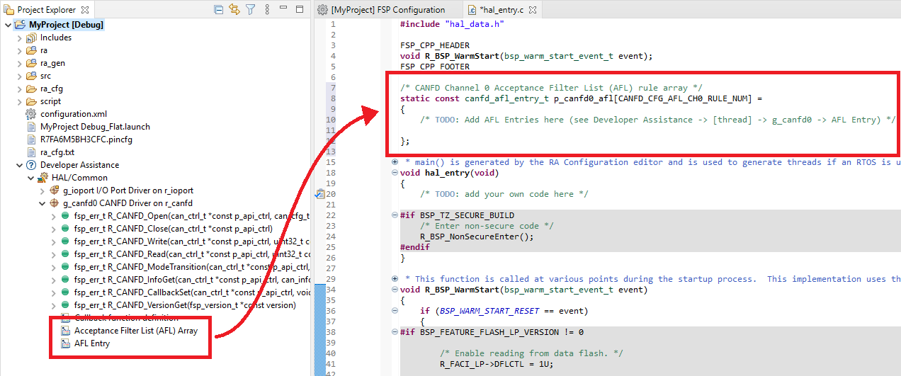
For an example configuration refer to the AFL Example below.
Flexible Data is an extension of the CAN protocol allowing for messages up to 64 bytes and higher data bitrates, among other features. The CANFD driver supports the following:
To specify one or more of these options when transmitting set can_frame_t::options with combined values from canfd_frame_options_t. Received messages will automatically have this field filled, if applicable.
For convenience, the baudrate of the CANFD peripheral is automatically set through the RA Configuration editor using a best effort approach.
Enabling Delay Compensation instructs the CANFD peripheral to measure TX to RX tranceiver delay and automatically adjust for it, improving the reliability of high-speed FD messages. This option may severely limit available bitrate settings depending on the source clock; it is highly recommended to check the generated values when enabled.
If the auto-generated baud settings cause deviation that is not tolerable by the application the user can override the auto-generated settings and put in manually calculated values through the RA Configuration editor. For more details on how the bitrate is calculated refer to the Clock Configuration section above.
The Sync Jump Width option specifies the maximum number of time quanta that the sample point may be delayed by to account for differences in oscillators on the bus. It should be set to a value between 1 and the configured Time Segment 2 value depending on the maximum permissible clock error.
The CANFD peripheral provides two types of error interrupts: Channel and Global. As the names imply, each channel has its own Channel Error interrupt but there is only one Global Error interrupt. Only the configured channel will receive callbacks for Global Errors.
Error interrupt callbacks will pass either CAN_EVENT_ERR_CHANNEL or CAN_EVENT_ERR_GLOBAL in the can_callback_args_t::event field. A second field, can_callback_args_t::error, provides the actual error code as canfd_error_t. Cast to this enum to retrieve the error condition. See the callback in the Basic Example below for a demonstration.
When DLC Checking is enabled messages are checked against the destination.minimum_dlc value of each AFL rule. If the data length of a message is less than this value the message will be rejected. When DLC checking is set to "Enabled w/truncate" in the RA Configuration editor any data in excess of the minimum DLC setting will be truncated and the DLC value for the frame will be set to match.
When an FD message is received with a DLC larger than the destination buffer an FD Payload Overflow interrupt is thrown (if configured). When Payload Overflow is set to "Truncate" the message will still be accepted but only data up to the buffer capacity will be preserved. The DLC value is unchanged in this case; any data beyond this value in the can_frame_t::data array should not be used.
The CANFD peripheral provides three basic test modes: Listen Only, Internal Loopback and External Loopback. Use R_CANFD_ModeTransition to switch to a test mode.
On some MCUs an additional "Internal Bus" test mode is available that allows connecting both CANFD channels together on an internal bus, effectively creating an internal CAN network. See the Internal Bus example below for details.
Developers should be aware of the following limitations when using CANFD:
The below is an example Acceptance Filter List (AFL) declaration with two rules.
This is a basic example of minimal use of the CANFD module in an application.
This example demonstrates sending an FD message with bitrate switching over external loopback. The CTX and CRX pins must be connected when using external loopback, though if a CAN tranciever is onboard a 120 Ohm resistor should be connected across CANH and CANL instead.
In this example two CANFD channels are connected to the Internal Bus test mode. API error checking has been omitted for clarity.
Data Structures | |
| struct | canfd_afl_entry_t |
| struct | canfd_global_cfg_t |
| struct | canfd_extended_cfg_t |
Enumerations | |
| enum | canfd_status_t |
| enum | canfd_error_t |
| enum | canfd_tx_buffer_t |
| enum | canfd_tx_mb_t |
| enum | canfd_rx_buffer_t |
| enum | canfd_rx_mb_t |
| enum | canfd_rx_fifo_t |
| enum | canfd_minimum_dlc_t |
| enum | canfd_frame_options_t |
| struct canfd_afl_entry_t |
AFL Entry (based on R_CANFD_CFDGAFL_Type in renesas.h)
| struct canfd_global_cfg_t |
CANFD Global Configuration
| struct canfd_extended_cfg_t |
CANFD Extended Configuration
| Data Fields | ||
|---|---|---|
| canfd_afl_entry_t const * | p_afl | AFL rules list. |
| uint64_t | txmb_txi_enable | Array of TX Message Buffer enable bits. |
| uint32_t | error_interrupts | Error interrupt enable bits. |
| can_bit_timing_cfg_t * | p_data_timing | FD Data Rate (when bitrate switching is used) |
| uint8_t | delay_compensation | FD Transceiver Delay Compensation (enable or disable) |
| canfd_global_cfg_t * | p_global_cfg | Global configuration (global error callback channel only) |
| enum canfd_status_t |
CANFD Status
| enum canfd_error_t |
CANFD Error Code
| enum canfd_tx_buffer_t |
CANFD Transmit Buffer (MB + CFIFO)
| enum canfd_tx_mb_t |
CANFD Transmit Message Buffer (TX MB)
| enum canfd_rx_buffer_t |
CANFD Receive Buffer (MB + FIFO + CFIFO)
| enum canfd_rx_mb_t |
CANFD Receive Message Buffer (RX MB)
| enum canfd_rx_fifo_t |
CANFD Receive FIFO (RX FIFO)
| enum canfd_minimum_dlc_t |
CANFD AFL Minimum DLC settings
| fsp_err_t R_CANFD_Open | ( | can_ctrl_t *const | p_api_ctrl, |
| can_cfg_t const *const | p_cfg | ||
| ) |
Open and configure the CANFD channel for operation.
Example:
| FSP_SUCCESS | Channel opened successfully. |
| FSP_ERR_ALREADY_OPEN | Driver already open. |
| FSP_ERR_IN_USE | Channel is already in use. |
| FSP_ERR_IP_CHANNEL_NOT_PRESENT | Channel does not exist on this MCU. |
| FSP_ERR_ASSERTION | A required pointer was NULL. |
| FSP_ERR_CAN_INIT_FAILED | The provided nominal or data bitrate is invalid. |
| FSP_ERR_CLOCK_INACTIVE | CANFD source clock is disabled (PLL or PLL2). |
| fsp_err_t R_CANFD_Close | ( | can_ctrl_t *const | p_api_ctrl | ) |
Close the CANFD channel.
| FSP_SUCCESS | Channel closed successfully. |
| FSP_ERR_NOT_OPEN | Control block not open. |
| FSP_ERR_ASSERTION | Null pointer presented. |
| fsp_err_t R_CANFD_Write | ( | can_ctrl_t *const | p_api_ctrl, |
| uint32_t | buffer, | ||
| can_frame_t *const | p_frame | ||
| ) |
Write data to the CANFD channel.
Example:
| FSP_SUCCESS | Operation succeeded. |
| FSP_ERR_NOT_OPEN | Control block not open. |
| FSP_ERR_CAN_TRANSMIT_NOT_READY | Transmit in progress, cannot write data at this time. |
| FSP_ERR_INVALID_ARGUMENT | Data length or buffer number invalid. |
| FSP_ERR_INVALID_MODE | An FD option was set on a non-FD frame. |
| FSP_ERR_ASSERTION | One or more pointer arguments is NULL. |
| FSP_ERR_UNSUPPORTED | FD is not supported on this MCU. |
| fsp_err_t R_CANFD_Read | ( | can_ctrl_t *const | p_api_ctrl, |
| uint32_t | buffer, | ||
| can_frame_t *const | p_frame | ||
| ) |
Read data from a CANFD Message Buffer or FIFO.
Example: snippet r_canfd_example.c R_CANFD_Read
| FSP_SUCCESS | Operation succeeded. |
| FSP_ERR_NOT_OPEN | Control block not open. |
| FSP_ERR_INVALID_ARGUMENT | Buffer number invalid. |
| FSP_ERR_ASSERTION | p_api_ctrl or p_frame is NULL. |
| FSP_ERR_BUFFER_EMPTY | Buffer or FIFO is empty. |
| fsp_err_t R_CANFD_ModeTransition | ( | can_ctrl_t *const | p_api_ctrl, |
| can_operation_mode_t | operation_mode, | ||
| can_test_mode_t | test_mode | ||
| ) |
Switch to a different channel, global or test mode.
Example:
| FSP_SUCCESS | Operation succeeded. |
| FSP_ERR_NOT_OPEN | Control block not open. |
| FSP_ERR_ASSERTION | Null pointer presented |
| FSP_ERR_INVALID_MODE | Cannot change to the requested mode from the current global mode. |
| fsp_err_t R_CANFD_InfoGet | ( | can_ctrl_t *const | p_api_ctrl, |
| can_info_t *const | p_info | ||
| ) |
Get CANFD state and status information for the channel.
| FSP_SUCCESS | Operation succeeded. |
| FSP_ERR_NOT_OPEN | Control block not open. |
| FSP_ERR_ASSERTION | Null pointer presented |
| fsp_err_t R_CANFD_CallbackSet | ( | can_ctrl_t *const | p_api_ctrl, |
| void(*)(can_callback_args_t *) | p_callback, | ||
| void *const | p_context, | ||
| can_callback_args_t *const | p_callback_memory | ||
| ) |
Updates the user callback with the option to provide memory for the callback argument structure. Implements can_api_t::callbackSet.
| FSP_SUCCESS | Callback updated successfully. |
| FSP_ERR_ASSERTION | A required pointer is NULL. |
| FSP_ERR_NOT_OPEN | The control block has not been opened. |
| FSP_ERR_NO_CALLBACK_MEMORY | p_callback is non-secure and p_callback_memory is either secure or NULL. |