|
RA Flexible Software Package Documentation
Release v6.5.1
|
|
|
RA Flexible Software Package Documentation
Release v6.5.1
|
|
Functions | |
| fsp_err_t | R_CTSU_Open (ctsu_ctrl_t *const p_ctrl, ctsu_cfg_t const *const p_cfg) |
| Opens and configures the CTSU driver module. Implements ctsu_api_t::open. More... | |
| fsp_err_t | R_CTSU_ScanStart (ctsu_ctrl_t *const p_ctrl) |
| This function should be called each time a periodic timer expires. If initial offset tuning is enabled, The first several calls are used to tuning for the sensors. Before starting the next scan, first get the data with R_CTSU_DataGet(). If a different control block scan should be run, check the scan is complete before executing. Implements ctsu_api_t::scanStart. More... | |
| fsp_err_t | R_CTSU_DataGet (ctsu_ctrl_t *const p_ctrl, uint16_t *p_data) |
| This function gets the sensor values as scanned by the CTSU. If initial offset tuning is enabled, The first several calls are used to tuning for the sensors. This function reads all previously corrected measured values into the specified buffer(p_data). CTSU1: The value passed through sensor CCO correction and moving average. CTSU2 JMM: The value passed through sensor CCO correction and moving average. CTSU2 VMM: Sensor passed through sensor CCO correction, frequency correction and moving average. The required buffer size varies depending on the measurement mode. Prepare the number of TS for the self-capacitance measurement and current measurement modes, and twice the number of matrixes for the mutual-capacitance measurement mode. In the case of CTSU2 JMM, data of 3 frequencies is stored, so prepare 3 times more. In diagnosis mode, if data collection has not been completed, the function returns FSP_ERR_CTSU_DIAG_NOT_YET. If data collection is completed, it will return FSP_SUCCESS, so please call R_CTSU_Diagnosis() to check the diagnosis result. In addition, if an error occurs in ADC measurement during the output‑voltage diagnosis, the function returns FSP_ERR_ABORTED. Implements ctsu_api_t::dataGet. More... | |
| fsp_err_t | R_CTSU_AutoJudgementDataGet (ctsu_ctrl_t *const p_ctrl, uint64_t *p_button_status) |
| This function gets the result of automatic judgement button. Call after the scan is completed. The result is 64-bit bitmaps and is stored in order of TS number for specified ctsu control. After the initial judgement, the baseline initialization bit is set and the automatic judgement threshold is set. This function is called only for automatic judgement. Implements ctsu_api_t::autoJudgementDataGet. More... | |
| fsp_err_t | R_CTSU_OffsetTuning (ctsu_ctrl_t *const p_ctrl) |
| This function tunes the offset register(SO). Call after the measurement is completed. If the return value is FSP_ERR_CTSU_INCOMPLETE_TUNING, tuning is not complete. Execute the measurement and this function call routine until the return value becomes FSP_SUCCESS. It is recommended to run this routine after R_CTSU_Open(). It can be recalled and tuned again. When the automatic judgement is enabled, after the offset tuning is completed,the baseline initialization bit flag is set. Implements ctsu_api_t::offsetTuning. More... | |
| fsp_err_t | R_CTSU_ScanStop (ctsu_ctrl_t *const p_ctrl) |
| This function scan stops the sensor as scanning by the CTSU. Implements ctsu_api_t::scanStop. More... | |
| fsp_err_t | R_CTSU_CallbackSet (ctsu_ctrl_t *const p_api_ctrl, void(*p_callback)(ctsu_callback_args_t *), void *const p_context, ctsu_callback_args_t *const p_callback_memory) |
| fsp_err_t | R_CTSU_Close (ctsu_ctrl_t *const p_ctrl) |
| Disables specified CTSU control block. Implements ctsu_api_t::close. More... | |
| fsp_err_t | R_CTSU_SpecificDataGet (ctsu_ctrl_t *const p_ctrl, uint16_t *p_specific_data, ctsu_specific_data_type_t specific_data_type) |
| This function gets the sensor specific data values as scanned by the CTSU. Call this function after calling the R_CTSU_DataGet() function. More... | |
| fsp_err_t | R_CTSU_DataInsert (ctsu_ctrl_t *const p_ctrl, uint16_t *p_insert_data) |
| This function inserts the value of the second argument as the measurement result value. Call this function after calling the R_CTSU_DataInsert() function. Implements ctsu_api_t::dataInsert. More... | |
| fsp_err_t | R_CTSU_Diagnosis (ctsu_ctrl_t *const p_ctrl) |
| Diagnosis the CTSU peripheral. Please call the function when the return value of R_CTSU_DataGet is FSP_SUCCESS. If an abnormality is detected in any of the diagnosis items, the corresponding diagnosis error is returned. If all diagnosis is complete normally, FSP_SUCCESS is returned. Implements ctsu_api_t::diagnosis. More... | |
This HAL driver supports the Capacitive Touch Sensing Unit (CTSU). It implements the CTSU Interface.
The capacitive touch sensing unit HAL driver (r_ctsu) provides an API to control the CTSU peripheral. This module performs capacitance measurement based on various settings defined by the configuration. This module is configured via the QE for Capacitive Touch.
| Device Group | Devices |
|---|---|
| RA0 | RA0L1 |
| RA2 | RA2A1, RA2E1, RA2L1 |
| RA4 | RA4L1, RA4M1, RA4M2, RA4M3, RA4W1 |
| RA6 | RA6M1, RA6M2, RA6M3, RA6M4, RA6M5 |
| Configuration | Options | Default | Description |
|---|---|---|---|
| Parameter Checking |
| Default (BSP) | If selected code for parameter checking is included in the build. |
| Support for using DTC |
| Disabled | Enable DTC support for the CTSU module. |
| Enable automatic judgment mode |
| Disabled | Enable or Disable automatic judgment mode. This feature is only for RA4L1 and RA0L1. |
| Interrupt priority level | MCU Specific Options | Priority level of all CTSU interrupt (CSTU_WR,CTSU_RD,CTSU_FN) |
| Configuration | Options | Default | Description |
|---|---|---|---|
| Scan Start Trigger | MCU Specific Options | CTSU Scan Start Trigger Select |
The first R_CTSU_Open function call sets the CTSU peripheral interrupts. The user should provide a callback function to be invoked at the end of CTSU scan sequence. The callback argument will contain information about the scan status.
The CTSU peripheral module uses PCLKB as its clock source. You can set the PCLKB frequency using the Clocks tab of the RA Configuration editor or by using the CGC Interface at run-time.
The TSn pins are sensor pins for CTSU.
The TSCAP pin is used for an internal low-pass filter and must be connected to an external decoupling capacitor.
CTSU module is a CTSU driver for Touch module. CTSU module assumes the access from Touch middleware layer, and it is also accessible from an user application.
The CTSU peripheral installed on RA family has three versions: CTSU, CTSU2, and CTSU2SLa. Each MCU device is equipped with the following version of the CTSU peripherals.
CTSU2SLa : RA4L1, RA0L1
CTSU2    : RA2E1, RA2L1
CTSU     : RA2A1, RA4M1, RA4M2, RA4M3, RA4W1, RA6M1, RA6M2, RA6M3, RA6M4, RA6M5
CTSU, CTSU2 and CTSU2SLa are functionally different, so these are described in this application note as below.
Common description for CTSU, CTSU2 and CTSULSa -> CTSU
Description only for CTSU                      -> CTSU1
Common description for CTSU2 only and CTSU2SLa -> CTSU2
Description only for CTSU2                     -> CTSU2 only
Description only for CTSU2SLa                  -> CTSU2SLa
Without mention, it means the common description for CTSU, CTSU2 and CTSU2SLa.
To understand this document, it is recommended to refer to Capacitive Sensor Microcontrollers CTSU Capacitive Touch Introduction Guide and Capacitive Touch Software Overview beforehand.
When developing an application using the module, it is recommended to use QE for Capacitive Touch.
CTSU module is a driver for controlling the CTSU peripheral.
By using configuration settings, CTSU module performs measurements corresponding to the electrodes connected to TS terminals and obtains the capacitance measurement values. Main functions are as follows:
The software configuration of a touch system is shown below.
Normally, CTSU module controls the CTSU peripheral and returns corrected measurement values. Therefore, to obtain button ON/OFF status, slider/wheel touch positions or pad touch coordinates in an application, CTSU module should be used in combination with TOUCH module.
In that case, TOUCH module calls CTSU module and converts the corrected measurement values obtained from CTSU module into button ON/OFF status, slider/wheel touch positions and pad touch coordinates. For details of the specific operation, refer to the usage note for TOUCH module.
If you want to perform your own touch judgment based on the corrected measurement values obtained from CTSU module, refer to the subsequent chapters.
Furthermore, by combining the hardware judgment implemented in CTSU2SLa peripheral (automatic judgment mode) with CTSU module, you can obtain touch ON/OFF results using CTSU module.
CTSU module can also be used to diagnose the internal circuits of the CTSU peripheral and obtain the diagnosis results.
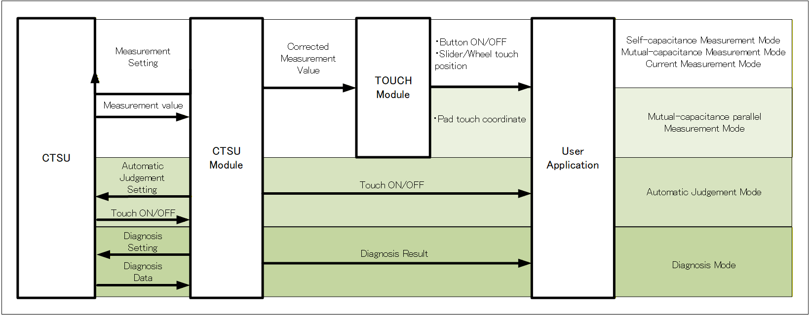
Figure Overview of software system shows an overview of the software system that illustrates how to use CTSU module.
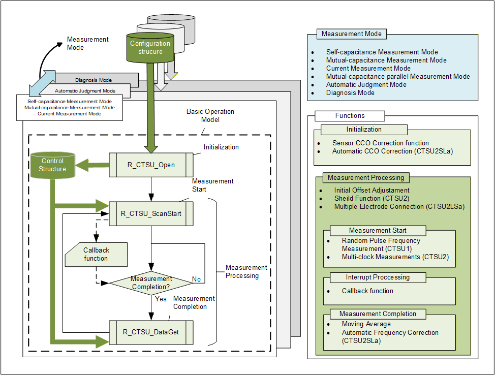
CTSU module defines measurement modes using a combination of API call groups and the associated structure information. The API call groups used in self-capacitance / mutual-capacitance / current measurement modes are treated as the basic operation model. For the operation models of mutual-capacitance parallel measurement, automatic judgment and diagnosis modes, refer to Measurement Mode.
In the basic operation model, you first call R_CTSU_Open() to initialize the CTSU peripheral and to read the configuration settings and create the configuration information in the control structure. After that, by periodically calling R_CTSU_ScanStart() (measurement start processing) and R_CTSU_DataGet() (measurement result acquisition processing), you can perform periodic measurement processing.
During measurement, the following interrupts occur: INTCTSUWR (register setting request interrupt), INTCTSURD (measurement result readout request interrupt), and INTCTSUFN (measurement completion interrupt). These interrupts are generated by the CTSU peripheral and processed by the module. After processing of INTCTSUFN completes, the module notifies the application of measurement completion via the callback function. After receiving the notification, perform the measurement result acquisition processing.
Note that INTCTSUWR and INTCTSURD processing can also use the DTC. For details on using the DTC, refer to Data Transfer.
In this module, data management is structured around two key data structures: the configuration structure and the control structure.
The configuration structure is used to set the measurement targets and measurement conditions. The target of a capacitance measurement is referred to as an element. In self-capacitance measurement mode, TS terminal serves as the measurement target, while in mutual-capacitance measurement mode, the targets are the matrix of transmitter TS terminals and receiver TS terminals. The measurement conditions include various parameters required for executing measurements using the CTSU peripheral, such as measurement mode, measurement time, measurement range, and trigger settings.
The measurement information defined in the configuration structure is copied into the control structure during the execution of R_CTSU_Open(). At the same time, buffers for storing measurement results are allocated, and internal flags and state information for managing measurement states are initialized. After initialization, only the control structure is referenced during the measurement process, enabling unified management of measurement settings, measurement states, and measurement results.
By preparing multiple sets of these structures, it becomes possible to run different measurement modes independently and in parallel, or to operate multiple measurement processes independently and in parallel even within the same measurement mode, provided the measurement targets and measurement conditions differ.
To simplify the configuration of these measurement settings, Renesas provides a development support tool called QE for Capacitive Touch. When creating applications that use this driver, it is recommended to use the touch interface configuration generated by QE for Capacitive Touch.
The term measurement mode collectively refers to the measurement processing determined by the measurement target, the measurement method, and the associated conditions. The available measurement modes differ depending on the functions of the CTSU peripheral.
The CTSU peripheral supports self-capacitance measurement mode, mutual-capacitance measurement mode, and diagnosis mode.
In addition to these, CTSU2 peripheral supports current measurement mode, the "CTSU2 only" peripheral supports mutual-capacitance parallel measurement mode, and CTSU2SLa peripheral supports automatic judgment mode.
Details of each measurement mode are described below.
The self-capacitance measurement mode is used to measure the capacitance of each terminal (TS).
The CTSU peripheral measures the terminals in ascending order according to TS numbers, then stores the data. For example, even if you want to use TS5, TS8, TS2, TS3 and TS6 in your application in that order, they will still be measured and stored in the order of TS2, TS3, TS5, TS6, and TS8. Therefore, you will need to reference buffer indexes [2], [4], [0], [1], and [3].
[CTSU1]
In default settings, the measurement period for each TS is wait-time plus approximately 526us.
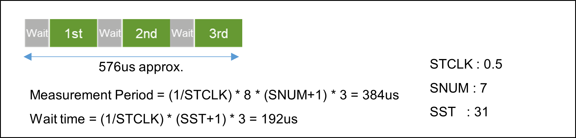
[CTSU2]
In default settings, the measurement period for each TS is approximately 576us.
The mutual-capacitance measurement mode is used to measure the capacitance generated between the receive TS (Rx) and transmit TS (Tx), and therefore requires at least two terminals.
CTSU2 peripheral measures all specified combinations of Rx and Tx. For example, when Rx is TS10 and TS3, and Tx is TS2, TS7 and TS4, the combinations are measured in the following order and the data is stored.
TS3-TS2, TS3-TS4, TS3-TS7, TS10-TS2, TS10-TS4, TS10-TS7
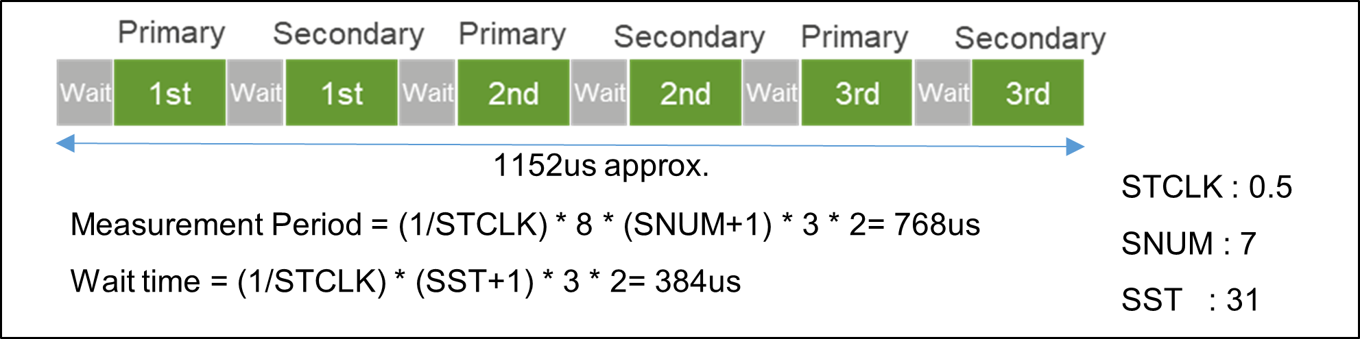
To measure the mutual-capacitance measurement generated between electrodes, CTSU2 peripheral performs the measurement process on the same electrode twice.
The mutual-capacitance measurement is obtained by inverting the phase relationship of the pulse output and switched capacitor in the primary and secondary corrected measurement values, and calculating the difference between the two measurements. This module does not calculate the difference, but outputs both primary and secondary corrected measurement result.
[CTSU1]
In default settings, the measurement period for each TS is twice of wait-time plus approximately 526us.
[CTSU2]
In default settings, the measurement period for each TS is approximately 1152us.
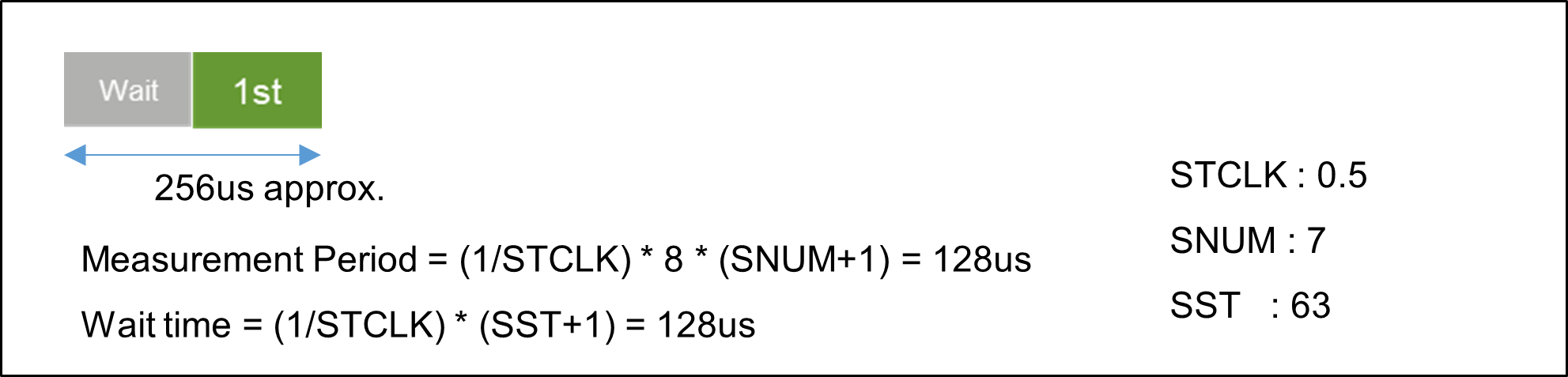
The current measurement mode is used to measure the minute current input to TS terminal.
The order of measurement and data storage is the same as that of the self-capacitance measurement mode.
As this does not involve the switched capacitor operation, the measurement is only performed once. The measurement period for one TS under default settings is approximately 256us. The current measurement mode requires a longer stable wait time than the other modes, so the SST is set to 63.
This mode provides fast measurement time by parallel scanning the RX lines with a CFC circuit. Operation is otherwise identical to normal CTSU mutual scanning.
In automatic judgment mode, CTSU2SLa peripheral is controlled to obtain touch judgment results. Since the touch judgment processing is performed by CTSU2SLa peripheral, touch judgment can be executed without using CPU processing. The DTC module is mandatory because DTC transfer are necessary to process the interrupts that occur during measurement. For details on the DTC, refer to Cooperation with other modules.
The operation flow of automatic judgment mode is shown below. First, initial offset tuning is performed using R_CTSU_ScanStart() and R_CTSU_OffsetTuning(). For details on initial offset tuning, refer to Initial Offset Adjustment. After initial offset tuning completes, automatic judgment measurement processing is performed using R_CTSU_ScanStart() and R_CTSU_AutoJudgementDataGet(). Note that the processing for the first measurement is different from that for the second and subsequent measurements:
First measurement:
The baseline for touch judgment is set. The first corrected measurement value is used as the baseline, and the touch judgment result is OFF.
Second and subsequent measurements:
Measurements are performed according to the measurement settings in the control structure, and touch judgment results are obtained.
By combining automatic judgment mode with measurement started by external triggers, you can create applications that perform touch judgment with low-power consumption. For more details and notes in that case, refer to Notes for low-power touch judgment. If you need more details on automatic judgment, refer to Functions and settings.

In low-power touch applications that combine CPU Snooze mode or Software Standby mode with automatic judgment mode, it is possible to keep the CPU in a low-power state while performing touch judgment and wake up the CPU only when a touch judgment result is ON.
However, CPU processing is required until the baseline is set. Therefore, switch to the low-power operation mode after executing the first R_CTSU_ScanStart() and R_CTSU_AutoJudgementDataGet(). For concrete operation examples, refer to "Smart Wakeup Solution" application note.
When using the automatic judgment mode, in addition to the standard measurement settings, it is necessary to modify certain macro definitions and configure the configuration structure for automatic judgment mode. These settings differ depending on the automatic judgment method, JMM or VMM.
First, to enable the automatic judgment feature, set CTSU_CFG_AUTO_JUDGE_ENABLE = 1. At the same time, enable the automatic CCO correction function by setting CTSU_CFG_AUTO_CORRECTION_ENABLE = 1. For VMM, also enable the automatic frequency correction function by setting CTSU_CFG_AUTO_MULTI_CLOCK_CORRECTION_ENABLE = 1.
Next, an example of configuration structure settings required in addition to the standard measurement settings is shown below for JMM. When using VMM, set jc = 0 and majirimd = 1.
.tlot     = 2, // Non-touch judgment continuous count : 3 times
.thot     = 2, // Touch judgment continuous count : 3 times
.jc       = 1, // Judgment by two or more frequency
.ajmmat   = 2, // Moving average : 2^2 times
.ajbmat   = 7, // Baseline average count : 2^(7+1) times
.majirimd = 0, // JMM
.mtucfen  = 1, // Enable mutual-capacitance calculation
.ajfen    = 1, // Enable automatic judgment
The following (a) ~ (e) describe the automatic judgment and its setting. In the case of JMM, (a) ~ (e) settings are set for each multi-clock measurement.
The CTSU peripheral has a function to diagnose its internal circuits. Diagnosis mode provides APIs that diagnose whether the internal circuits are operating correctly.
In this mode, CTSU internal circuits are diagnosed and, if an abnormality occurs, the result can be obtained as an error.
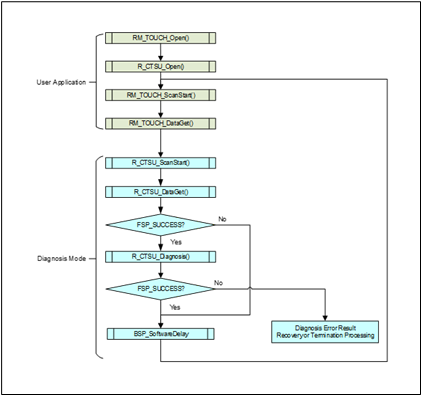
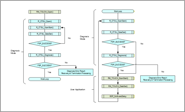
The diagnosis contents differ between CTSU1 and CTSU2, and therefore the operation model (API call sequence) also differs.
To enable diagnosis mode, set CTSU_CFG_DIAG_SUPPORT_ENABLE = 1.
[CTSU1]
| Order | Diagnosis items |
|---|---|
| 1 | Over Voltage Detection Diagnosis |
| 2 | CCO High Diagnosis |
| 3 | CCO Low Diagnosis |
| 4 | SSCG Oscillator Diagnosis |
| 5 | Current Offset Diagnosis |
[CTSU2]
| Order | Diagnosis items | Onetime / Repeat (※1) |
|---|---|---|
| 1 | Output Voltage Diagnosis | Repeat |
| 2 | Over Voltage Detection Diagnosis | One-time |
| 3 | Over Current Detection Diagnosis | One-time |
| 4 | Load Resistance Diagnosis | Repeat |
| 5 | Current Offset Diagnosis | One-time |
| 6 | SENSCLK Frequency Diagnosis | Repeat |
| 7 | SUCLK Frequency Diagnosis | Repeat |
| 8 | SUCLK Clock Recovery Diagnosis | Repeat |
| 9 | CFC Oscillator Gain Diagnosis (※2) | Repeat |
※1 "One-time" assumes diagnosis is performed once after reset. "Repeat" assumes periodic measurements.
※2 This diagnosis can only be used during Mutual-capacitance parallel Measurement Mode (CTSU2 only).
|Member Name|Setting| |--------—|----—| |ctsu_element_cfg_t| |so|0x00| |snum|0x07| |sdpa|Measurement setting for overcurrent detection| |ctsu_cfg_t| |md|CTSU_MODE_DIAGNOSIS_SCAN| |ctsuchacN (N=0~4)|Measurement terminal for overcurrent detection|
$$ I = fCV $$
$$ SDPA_1 = ((SDPA_0 + 1)*I_0 / 100) - 1 $$
Make sure that the sensor‑drive pulse frequency set by SDPA1 provides enough time to charge and discharge the target TS terminal.
CTSU module supports the following functions.
CTSU2 has two judgment type, which differ in processing and output data.
It is common to get three raw value for each element and calculate CCO correction, and then performs different processing.
Measurements can be started by a software trigger or by an external event triggered by Event Link Controller (ELC).
As the measurement process is carried out by CTSU2 peripheral, it does not use up main processor processing time.
CTSU module processes INTCTSUWR and INTCTSURD if generated during a measurement. Data Transfer Controller (DTC) can also be used for these processes.
When the measurement complete interrupt (INTCTSUFN) process is complete, the application is notified in a callback function. Make sure you obtain the measurement results before the next measurement is started as internal processes are also executed when a measurement is completed.
Start the measurement with API function R_CTSU_ScanStart().
Obtain the measurement results with API function R_CTSU_DataGet().
The number of arrays in the second argument of R_CTSU_DataGet() is different between VMM and JMM.
VMM returns one measurement result for each element.
JMM returns three measurement results for each element.
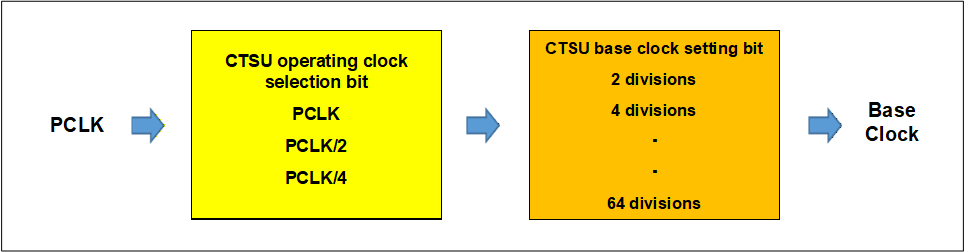
The drive pulse used for the measurement is a pulse with phase shifting and frequency spreading applied to the configured base clock.
The base-cloclk setting generally uses the value tuned with QE for Capacitive Touch.
This module is fixed at initialization and sets the following.
CTSUSOFF = 0, CTSUSSMOD = 0, CTSUSSCNT = 3
The drive frequency is calculated as below.
It is determined by PCLK frequency input to CTSU, CTSU Count Source Select bit(CTSUCLK), and CTSU Sensor Drive pulse Division Control bit(CTSUSDPA). For example, If it is set PCLK =32MHz, CTSUCLK = PLCK/2, and CTSUSDPA = 1/16, then drive frequency is 0.5MHz. CTSUSDPA can change for each TS port.
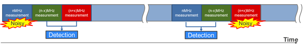
CTSU2 peripheral can measure in one of four drive frequencies to avoid synchronous noise.
By default, this module measures at three different frequencies and makes a majority judgment on the three measurement results obtained.
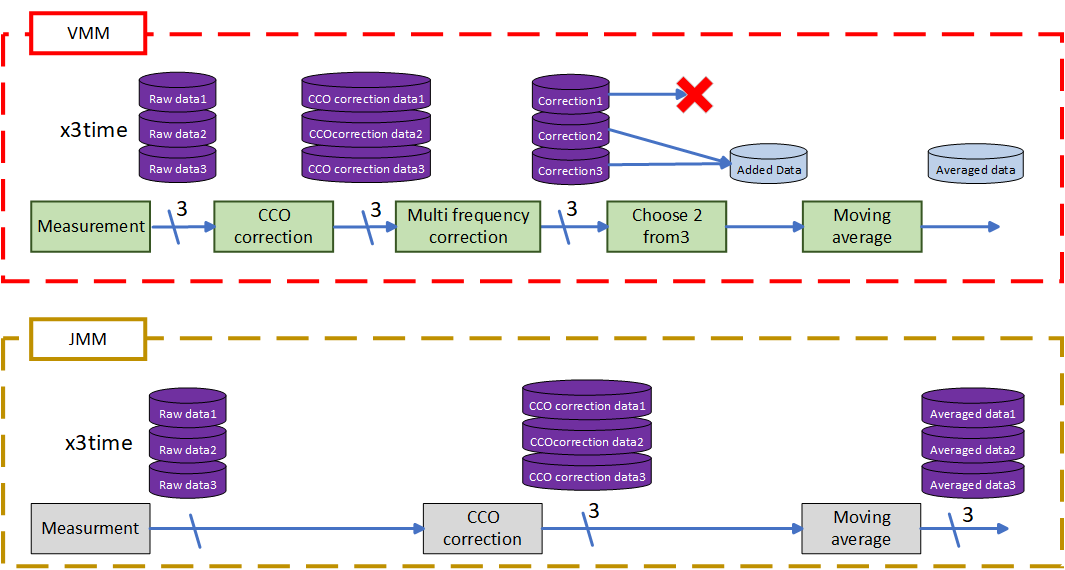
There are two types of majority judgment modes for the three measurement results: JMM (Judgment Majority Mode) and VMM (Value Majority Mode). JMM only supports self-capacitance buttons and mutual-capacitance buttons.
The figure below shows the flowchart of JMM and VMM with Touch module.
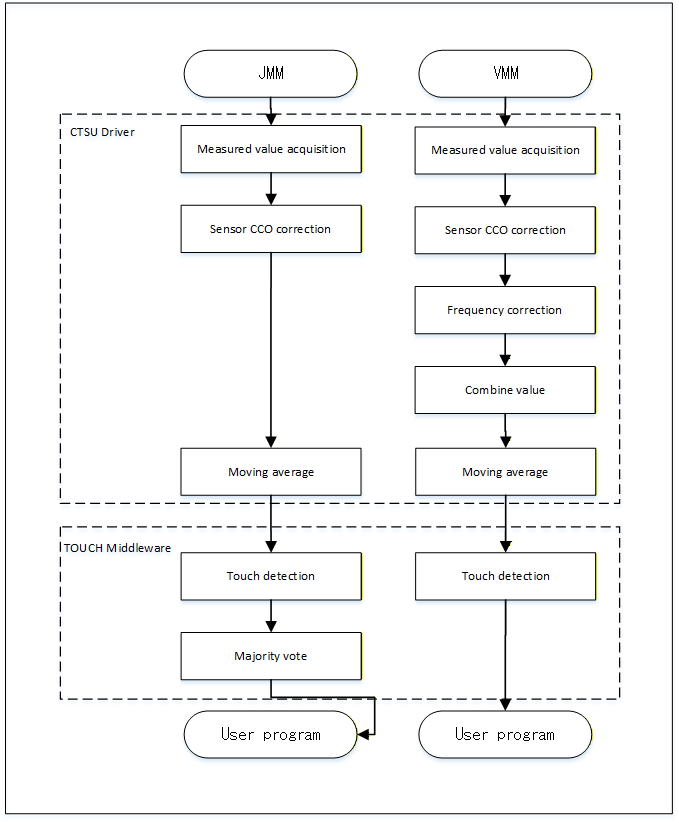
JMM performs CCO correction on the three measurement values, then makes a touch judgment for each of them, and determines the final touch result by majority vote of the three judgments.
VMM performs CCO correction on the three measurement values, applies frequency correction to convert them to the measurement value at the first frequency, and then selects the two values that are close to each other. These two values are added together, and the result is treated as a measurement value with double the measurement time. Touch judgment is made based on this corrected measurement value.
Example VMM Calculations
From the frequency-corrected measurement values 1, 2, and 3, the difference values 1, 2, and 3 for each pair are calculated, and the smaller pair is selected by comparing the absolute values of the difference values. To prevent variation in the corrected measurement values, a combination of value 1 and value 2 is given a weight to be selected. When comparing value 3, multiply the difference value 2 by 2 and multiply the difference value 3 by 1.5.
| Corrected Measurement Value 1 | Corrected Measurement Value 2 | Corrected Measurement Value 3 | Difference value 1 | Difference value 2 | Difference value 3 | Result | Added Value |
|---|---|---|---|---|---|---|---|
| 7734 | 7734 | 7663 | 0 | 71 | 71 | Value 1+2 | 15468 |
| 7689 | 7739 | 7666 | 50 | 23 | 73 | Value 1+3 | 15355 |
| 7734 | 7679 | 7664 | 55 | 70 | 15 | Value 2+3 | 15343 |
| 7721 | 7719 | 7694 | 2 | 27 | 25 | Value 1+2 | 15440 |
| 7716 | 7747 | 7693 | 31 | 23 | 54 | Value 1+2 | 15463 |
You can set JMM or VMM for each touch interface configuration. If the ctsu_cfg_t member "majority_mode" is set to 1, it works in JMM, and if it is set to 0, it works in VMM.
R_CTSU_DataGet() can get the data after conducting the moving average. To retrieve the data for each of the previous processes R_CTSU_SpecificDataGet() use. These data can also be used to determine the data with its own noise filter in Touch module. See R_CTSU_DataGet() and R_CTSU_SpecificDataGet() for more information.
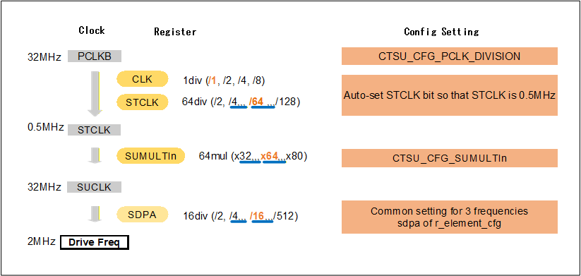
Drive pulse frequency is determined based on the config settings. The module sets registers according to the config settings, and sets the three drive frequencies.
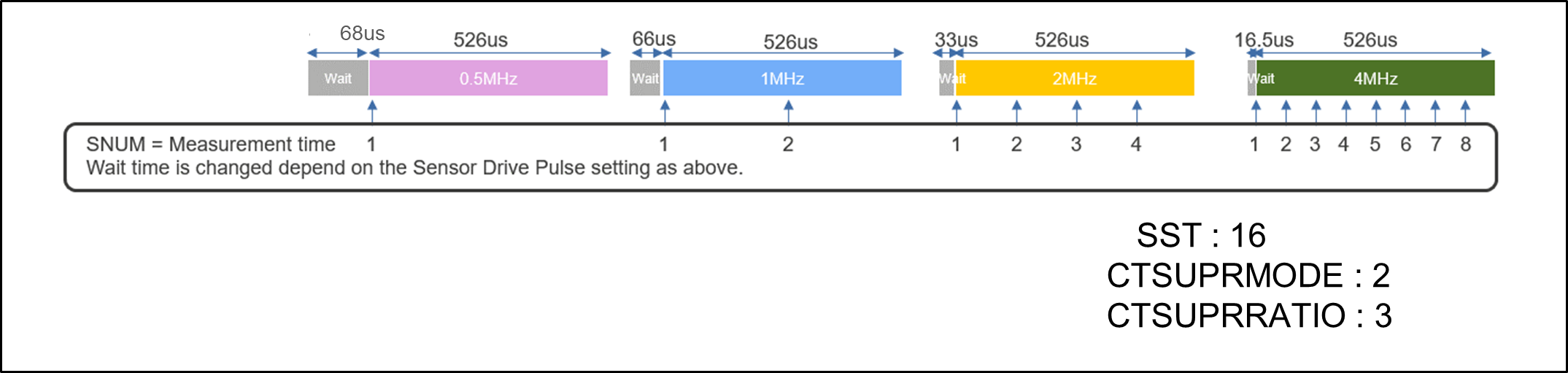
Drive pulse frequency is calculated in the following equation:
$$ f_{DrivePulse} = F_{PCLKB} / (2^{CLK}*2*(STCLK + 1)) * (SUMULTI_n + 1) / (2*(SDPA + 1)), n = 0, 1, 2 $$ The figure below shows the settings for generating a 2MHz drive pulse frequency when PCLKB frequency is 32 MHz. SDPA can be set for each touch interface configuration.
The CTSU peripheral has a built-in correction circuit to handle the potential microvariations related to the manufacturing process of the sensor CCO MCU.
This module uses the correction circuit during initialization after power-on to generate a correction coefficient to ensure accurate sensor measurement values. This correction coefficient is used to correct the measurement value.
The CTSU peripheral was designed with a built-in offset current circuit in consideration of the amount of change in current due to touch. The offset current circuit cancels enough of the parasitic capacitance for it to fit within the sensor CCO dynamic range.
This module adjusts the offset current setting so that the corrected measurement value reaches the target value. As the adjustment uses the normal measurement process, R_CTSU_ScanStart() and R_CTSU_DataGet() must be repeated several times after startup. Because the ctsu_element_cfg_t member "so" is the starting point for adjustments, you can set the appropriate value for "so" in order to reduce the number of times the two functions must be run to complete the adjustment. Normally, the value used for "so" is a value adjusted by QE for Capacitive Touch.
For CTSU2, this feature can be turned off in the config.
Default target value (CTSU)
| Mode | CTSU1 target value | CTSU2 target value |
|---|---|---|
| Self-capacitance | 15360 (37.5%) | 11520 (37.5%) |
| Self-capacitance using active shield | - | 4608 (15%) |
| Mutual-capacitance | 10240 (25%) | 7680 (25%) |
The percentage is based on 100% being the maximum input current applied to the CCO.
CTSU1: 100% is the measured value 40960 when the measurement time is 526us(base time).
CTSU2: 100% is the measured value 30720 when the measurement time is 256us(base time).
When the measurement time is changed, the target value is adjusted by the ratio with the base time.
Example of target value in combination of CTSUSNUM and CTSUSDPA
| Target value | CTSUSNUM | CTSUSDPA | Measurement time |
|---|---|---|---|
| 15360 | 0x3 | 0x7 | 526usec |
| 30720 | 0x7 | 0x7 | 1052usec |
| 30720 | 0x3 | 0xF | 1052usec |
| 7680 | 0x1 | 0x7 | 263usec |
| 7680 | 0x3 | 0x3 | 263usec |
The measurement time changes depending on the combination of CTSUSNUM and CTSUSDPA.
Recommended CTSUPRRATIO and CTSUPRMODE are used. Changing this value is deprecated. For detail, refer to the hardware manual of each capacitive touch sensor.
| Target value | Target value (multi-clock) | CTSUSNUM | Measurement time |
|---|---|---|---|
| 5760 | 11520 (128us + 128us) | 0x7 | 128usec |
| 11520 | 23040 (256us + 256us) | 0xF | 256usec |
| 2880 | 5460 (64us + 64us) | 0x3 | 64usec |
The measurement time changes depending on CTSUSNUM. If STCLK cannot be set to 0.5MHz, it will not support the table above. Regarding STCLK, refer to the hardware manual.
This function calculates the moving average of the measured results.
Set the number of times the moving average should be calculated in the config settings.
When an abnormal condition is detected during measurement, the CTSU peripheral sets the corresponding status register.
In the measurement-completion interrupt handler, the module reads CTSUSOVF from the status register and CTSUICOMP from the error status register for CTSU1, and reads ICOMP1, ICOMP0, and SENSOVF from the status register for CTSU2. After the registers are read, the status registers are cleared. The details of the abnormal condition can be checked by referring to the member "event" of the ctsu_callback_args_t structure passed to the callback function.
CTSU2 peripheral has a built-in function that outputs a shield signal in phase with the drive pulse from the shield terminal and the non-measurement terminal in order to shield against external influences while suppressing any increase in parasitic capacitance. This function can only be used during Self-capacitance Measurement.
This module allows the user to set a shield for each touch interface configuration.
For example, for the electrode configuration shown below, the members of ctsu_cfg_t should be set as follows. Other members have been omitted for the example.
.txvsel     = CTSU_TXVSEL_INTERNAL_POWER,
.txvsel2    = CTSU_TXVSEL_MODE,
.md         = CTSU_MODE_SELF_MULTI_SCAN,
.posel      = CTSU_POSEL_SAME_PULSE,
.ctsuchac0  = 0x0F,
.ctsuchtrc0 = 0x08,

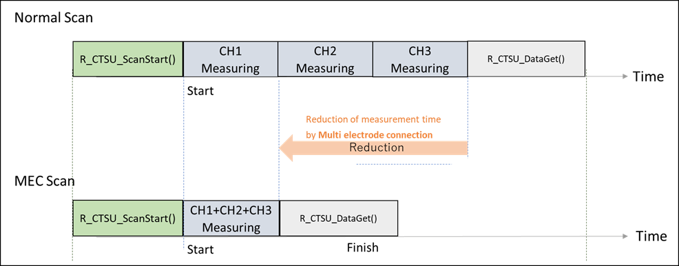
CTSU2SLa peripheral has MEC (Multiple Electrode Connection) function that connects multiple electrodes and measures them as a single electrode. This feature is only available in Self-capacitance Measurement Mode.
This is an example when using three electrodes. In normal times, normal measurement is performed, and 3 channels are measured to get each corrected measured value. In power saving, MEC measurement is performed, and one channel is measured by combining three channels to acquire one corrected measured value.
The figure below shows a compare of time of normal measurement and MEC measurement. Since multi channels are measured at the same time, the measurement time is shortened.
To enable the code for MEC feature, set CTSU_CFG_MULTIPLE_ELECTRODE_CONNECTION_ENABLE to 1.
When using MEC, create a touch interface configuration different from the normal touch interface configuration for the same TS. The following settings are required for the touch interface configuration for MEC measurement.
To enable MEC for touch interface configurations by setting tsod in ctsu_cfg_t to 1.
Set mec_ts of ctsu_cfg_t to one of TS numbers to be measured.
If you want to use the shield function at the same time, set TS number of the shield terminal in mec_shield_ts of ctsu_cfg_t. In this case, only one TS can be used as a shield terminal.
Set num_rx of ctsu_cfg_t to 1.
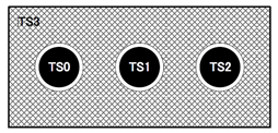
For example, in the case of the electrode configuration shown below, set the members of ctsu_cfg_t as shown below. Other members are omitted here.
.tsod          = 1,
.mec_ts        = 0,
.mec_shield_ts = 3,
.num_rx        = 1,
The automatic CCO correction function is a feature that performs sensor CCO correction calculations inside CTSU2SLa peripheral. For details on sensor CCO correction, refer to Sensor CCO Correction function.
Because CTSU2SLa peripheral processes the sensor CCO correction calculation internally, the corrected data can be obtained without using software‑based correction processing, and no processing time is consumed on the main processor.
To enable the automatic CCO correction function, set CTSU_CFG_AUTO_CORRECTION_ENABLE to 1.
The automatic frequency‑correction function is a feature that performs multi-clock correction inside CTSU2SLa peripheral.
Because CTSU2SLa peripheral processes the multi-clock correction calculation internally, the corrected data can be obtained without using software‑based correction processing, and no processing time is consumed on the main processor.
To enable the automatic frequency correction function, set CTSU_CFG_AUTO_MULTI_CLOCK_CORRECTION_ENABLE to 1.
When using the automatic frequency‑correction function, also enable the automatic CCO correction function.
Some functions of CTSU module require cooperation with other modules.
| Module | Application | Integration Method |
|---|---|---|
| Timers (r_agt, r_tau, ect.) | Start measurement via external trigger | Add FSP module for the timer used (such as AGT). Configure it in the application as appropriate. |
| ELC (r_elc) | Start measurement via external trigger | Add ELC module. Configure it in the application according to the timer used. |
| LPM (r_lpm) | Low power touch operation | Add LPM module. |
| Transfer (r_dtc) | Data transfer for INTCTSUWR and INTCTSURD during measurement | Add DTC module. CTSU module already uses DTC APIs internally. |
| ADC (r_adc/r_adc_d) | Diagnose Output voltage in CTSU2 diagnosis function | Add ADC module. CTSU module already uses ADC APIs internally. |
Measurement can be started by either a software trigger or an external trigger. Select according to your system requirements.
Software trigger
Measurement starts when R_CTSU_ScanStart() sets the measurement‑start bit to 1. Since configuration for the touch interface is performed before setting this bit, there is a small delay between the API call and the actual start of measurement. However, this delay is very small compared with the measurement time, so the software trigger, which is simpler to configure, is generally recommended.
External trigger
After R_CTSU_ScanStart() sets the measurement‑start trigger‑selection bit and the measurement‑start bit to 1, CTSU enters a trigger‑wait state. Measurement starts upon receiving an event. Generally, timers are used to measure periodically. Use this method when the small delay of the software trigger cannot be tolerated or when low‑power operation is required. When using multiple measurement modes with external triggers, configure the next measurement mode by calling R_CTSU_ScanStart() after measurement of one mode completes.
When using an external trigger, configure the settings in the Stacks tab as follows:
LPM module reduces power consumption by managing transitions between operating control modes and controlling low‑power states. By combining the LPM module with the automatic judgment mode of CTSU2LSa, low‑power touch operation can be achieved.
When using the LPM module with CTSU, configure the settings in the Stacks tab as follows:
In CTSU module, DTC can be used instead of CPU to handle INTCTSUWR and INTCTSURD processing during measurement. In automatic judgment mode, DTC module must be used. In other measurement modes, DTC is optional.
When using DTC module with CTSU, configure the settings in the Stacks tab as follows:
In CTSU2 diagnosis mode, ADC measurements are required for certain steps. Therefore, add ADC module to the Stacks tab and configure the settings as follows:
For RA0L1 (using the r_adc_d module):
For other devices (using the r_adc module):
If you also use ADC in the application outside diagnosis mode, release ADC resources by closing ADC module at the following timings:
ADC module can be closed by calling R_ADC_Close().
If you do not close ADC module, R_CTSU_Diagnosis() returns FSP_ERR_ABORTED. In that case, close ADC and ensure that ADC measurement by CTSU module can be performed in the next diagnosis mode execution.
Measurements are initiated by a software trigger or an external event which is triggered by Event Link Controller (ELC).
The most common method is using a timer to carry out periodic measurements. Make sure to set the timer interval to allow the measurement and internal value update processes to complete before the next measurement period. The measurement period differs according to touch interface configuration and measurement mode.
The execution timing of software triggers and external triggers differ slightly.
Since a software trigger sets the start flag after setting the touch interface configuration with R_CTSU_ScanStart(), there is a slight delay after the timer event occurrence. However, as the delay is much smaller than the measurement period, a software trigger is recommended for most instances as it is easy to set.
An external trigger is recommended for applications in which this slight delay is not acceptable or that require low-power consumption operations. When using an external trigger with multiple touch interface configurations, use R_CTSU_ScanStart() to set another touch interface configuration after one measurement is completed.
In r_ctsu and rm_touch module, Non-Secure Callable Guard Functions are only generated from QE for Capacitive Touch. QE can be used for tuning in secure or flat project, but not in non-secure project. If you want to use in non-secure project, copy the output file from secure or flat project. Refer to QE Help for more information.
The flow of storing data in RAM is as follows.
(CTSU1)
(CTSU2 VMM)
(CTSU2 JMM)
There are two ways to add the user's filter.
Please check example.
User's filter additional Example
This is a basic example of minimal use of CTSU in an application.
This is a optional example of using both Self-capacitance and Mutual-capacitance configurations in the same project.
This is an example of offset adjustment using R_CTSU_OffsetTuning().
After completing R_CTSU_Open (), perform initial offset adjustment.
Offset adjustment is performed again when the parasitic capacitance changes significantly due to changes in the surrounding environment and the count value becomes an abnormal value.
This is a Diagnosis function example of using the configuration in the basic example.
CTSU1 Diagnosis function example:
CTSU2 Diagnosis function example:
This is a user's filter additiional example of using the configuration in the basic example.
To perform user's filter calculation, change the num_moving_average of the element in the target ctsu_cfg_t to 1.
Perform user filter calculation and use R_CTSU_DataInsert() to input user filter calculation result.
Using the correction data obtained by R_CTSU_SpecificDataGet(). Perform user majority decision calculation & filter calculation and use R_CTSU_DataInsert() to input user majority decision calculation & filter calculation result.
Data Structures | |
| struct | ctsu_ctsuwr_t |
| struct | ctsu_self_buf_t |
| struct | ctsu_mutual_buf_t |
| struct | ctsu_correction_info_t |
| struct | ctsu_instance_ctrl_t |
Enumerations | |
| enum | ctsu_state_t |
| enum | ctsu_tuning_t |
| enum | ctsu_correction_status_t |
| enum | ctsu_range_t |
| struct ctsu_ctsuwr_t |
| struct ctsu_self_buf_t |
| struct ctsu_mutual_buf_t |
| struct ctsu_correction_info_t |
Correction information
| Data Fields | ||
|---|---|---|
| ctsu_correction_status_t | status | Correction status. |
| ctsu_ctsuwr_t | ctsuwr | Correction scan parameter. |
| volatile ctsu_self_buf_t | scanbuf | Correction scan buffer. |
| uint8_t | calculation_error | Overflow or underflow in correction calclation. |
| uint16_t | first_val | 1st correction value |
| uint16_t | second_val | 2nd correction value |
| uint32_t | first_coefficient | 1st correction coefficient |
| uint32_t | second_coefficient | 2nd correction coefficient |
| uint32_t | ctsu_clock | CTSU clock [MHz]. |
| struct ctsu_instance_ctrl_t |
CTSU private control block. DO NOT MODIFY. Initialization occurs when R_CTSU_Open() is called.
Data Fields | |
| uint32_t | open |
| Whether or not driver is open. | |
| volatile ctsu_state_t | state |
| CTSU run state. | |
| ctsu_cap_t | cap |
| CTSU Scan Start Trigger Select. | |
| ctsu_md_t | md |
| CTSU Measurement Mode Select(copy to cfg) | |
| ctsu_tuning_t | tuning |
| CTSU Initial offset tuning status. | |
| uint16_t | num_elements |
| Number of elements to scan. | |
| uint16_t | wr_index |
| Word index into ctsuwr register array. | |
| uint16_t | rd_index |
| Word index into scan data buffer. | |
| uint8_t * | p_element_complete_flag |
| Pointer to complete flag of each element. g_ctsu_element_complete_flag[] is set by Open API. | |
| int32_t * | p_tuning_diff |
| Pointer to difference from base value of each element. g_ctsu_tuning_diff[] is set by Open API. | |
| uint16_t | average |
| CTSU Moving average counter. | |
| uint16_t | num_moving_average |
| Copy from config by Open API. | |
| uint8_t | ctsucr1 |
| Copy from (atune1 << 3, md << 6) by Open API. CLK, ATUNE0, CSW, and PON is set by HAL driver. | |
| ctsu_ctsuwr_t * | p_ctsuwr |
| CTSUWR write register value. g_ctsu_ctsuwr[] is set by Open API. | |
| ctsu_self_buf_t * | p_self_raw |
| Pointer to Self raw data. g_ctsu_self_raw[] is set by Open API. | |
| uint16_t * | p_self_corr |
| Pointer to Self correction data. g_ctsu_self_corr[] is set by Open API. | |
| uint16_t * | p_self_mfc |
| Pointer to Self multi frequency correction data. g_ctsu_self_mfc[] is set by Open API. | |
| ctsu_data_t * | p_self_data |
| Pointer to Self moving average data. g_ctsu_self_data[] is set by Open API. | |
| ctsu_mutual_buf_t * | p_mutual_raw |
| Pointer to Mutual raw data. g_ctsu_mutual_raw[] is set by Open API. | |
| uint16_t * | p_mutual_pri_corr |
| Pointer to Mutual primary correction data. g_ctsu_mutual_pri_corr[] is set by Open API. | |
| uint16_t * | p_mutual_snd_corr |
| Pointer to Mutual secondary correction data. g_ctsu_mutual_snd_corr[] is set by Open API. | |
| uint16_t * | p_mutual_pri_mfc |
| Pointer to Mutual primary multi frequency correction data. g_ctsu_pri_mutual_mfc[] is set by Open API. | |
| uint16_t * | p_mutual_snd_mfc |
| Pointer to Mutual secondary multi frequency correction data. g_ctsu_snd_mutual_mfc[] is set by Open API. | |
| ctsu_data_t * | p_mutual_pri_data |
| Pointer to Mutual primary moving average data. g_ctsu_mutual_pri_data[] is set by Open API. | |
| ctsu_data_t * | p_mutual_snd_data |
| Pointer to Mutual secondary moving average data. g_ctsu_mutual_snd_data[] is set by Open API. | |
| ctsu_correction_info_t * | p_correction_info |
| Pointer to correction info. | |
| ctsu_txvsel_t | txvsel |
| CTSU Transmission Power Supply Select. | |
| ctsu_txvsel2_t | txvsel2 |
| CTSU Transmission Power Supply Select 2 (CTSU2) | |
| uint8_t | ctsuchac0 |
| TS00-TS07 enable mask. | |
| uint8_t | ctsuchac1 |
| TS08-TS15 enable mask. | |
| uint8_t | ctsuchac2 |
| TS16-TS23 enable mask. | |
| uint8_t | ctsuchac3 |
| TS24-TS31 enable mask. | |
| uint8_t | ctsuchac4 |
| TS32-TS39 enable mask. | |
| uint8_t | ctsuchtrc0 |
| TS00-TS07 mutual-tx mask. | |
| uint8_t | ctsuchtrc1 |
| TS08-TS15 mutual-tx mask. | |
| uint8_t | ctsuchtrc2 |
| TS16-TS23 mutual-tx mask. | |
| uint8_t | ctsuchtrc3 |
| TS24-TS31 mutual-tx mask. | |
| uint8_t | ctsuchtrc4 |
| TS32-TS39 mutual-tx mask. | |
| uint16_t | self_elem_index |
| self element index number for Current instance. | |
| uint16_t | mutual_elem_index |
| mutual element index number for Current instance. | |
| uint16_t | ctsu_elem_index |
| CTSU element index number for Current instance. | |
| ctsu_cfg_t const * | p_ctsu_cfg |
| Pointer to initial configurations. | |
| IRQn_Type | write_irq |
| Copy from config by Open API. CTSU_CTSUWR interrupt vector. | |
| IRQn_Type | read_irq |
| Copy from config by Open API. CTSU_CTSURD interrupt vector. | |
| IRQn_Type | end_irq |
| Copy from config by Open API. CTSU_CTSUFN interrupt vector. | |
| void(* | p_callback )(ctsu_callback_args_t *) |
| Callback provided when a CTSUFN occurs. | |
| uint8_t | interrupt_reverse_flag |
| Flag in which read interrupt and end interrupt are reversed. | |
| ctsu_event_t | error_status |
| error status variable to send to QE for serial tuning. | |
| ctsu_callback_args_t * | p_callback_memory |
| Pointer to non-secure memory that can be used to pass arguments to a callback in non-secure memory. | |
| void * | p_context |
| Placeholder for user data. | |
| bool | serial_tuning_enable |
| Flag of serial tuning status. | |
| uint16_t | serial_tuning_mutual_cnt |
| Word index into ctsuwr register array. | |
| uint16_t | tuning_self_target_value |
| Target self value for initial offset tuning. | |
| uint16_t | tuning_mutual_target_value |
| Target mutual value for initial offset tuning. | |
| uint8_t | tsod |
| Copy from tsod by Open API. | |
| uint8_t | mec_ts |
| Copy from mec_ts by Open API. | |
| uint8_t | mec_shield_ts |
| Copy from mec_shield_ts by Open API. | |
| enum ctsu_state_t |
| enum ctsu_tuning_t |
| enum ctsu_range_t |
| fsp_err_t R_CTSU_Open | ( | ctsu_ctrl_t *const | p_ctrl, |
| ctsu_cfg_t const *const | p_cfg | ||
| ) |
Opens and configures the CTSU driver module. Implements ctsu_api_t::open.
Example:
| FSP_SUCCESS | CTSU successfully configured. |
| FSP_ERR_ASSERTION | Null pointer, or one or more configuration options is invalid. |
| FSP_ERR_ALREADY_OPEN | Module is already open. This module can only be opened once. |
| FSP_ERR_INVALID_ARGUMENT | Configuration parameter error. |
| fsp_err_t R_CTSU_ScanStart | ( | ctsu_ctrl_t *const | p_ctrl | ) |
This function should be called each time a periodic timer expires. If initial offset tuning is enabled, The first several calls are used to tuning for the sensors. Before starting the next scan, first get the data with R_CTSU_DataGet(). If a different control block scan should be run, check the scan is complete before executing. Implements ctsu_api_t::scanStart.
Example:
| FSP_SUCCESS | CTSU successfully configured. |
| FSP_ERR_ASSERTION | Null pointer passed as a parameter. |
| FSP_ERR_NOT_OPEN | Module is not open. |
| FSP_ERR_CTSU_SCANNING | Scanning this instance or other. |
| FSP_ERR_CTSU_NOT_GET_DATA | The previous data has not been retrieved by DataGet. |
| fsp_err_t R_CTSU_DataGet | ( | ctsu_ctrl_t *const | p_ctrl, |
| uint16_t * | p_data | ||
| ) |
This function gets the sensor values as scanned by the CTSU. If initial offset tuning is enabled, The first several calls are used to tuning for the sensors. This function reads all previously corrected measured values into the specified buffer(p_data). CTSU1: The value passed through sensor CCO correction and moving average. CTSU2 JMM: The value passed through sensor CCO correction and moving average. CTSU2 VMM: Sensor passed through sensor CCO correction, frequency correction and moving average. The required buffer size varies depending on the measurement mode. Prepare the number of TS for the self-capacitance measurement and current measurement modes, and twice the number of matrixes for the mutual-capacitance measurement mode. In the case of CTSU2 JMM, data of 3 frequencies is stored, so prepare 3 times more. In diagnosis mode, if data collection has not been completed, the function returns FSP_ERR_CTSU_DIAG_NOT_YET. If data collection is completed, it will return FSP_SUCCESS, so please call R_CTSU_Diagnosis() to check the diagnosis result. In addition, if an error occurs in ADC measurement during the output‑voltage diagnosis, the function returns FSP_ERR_ABORTED. Implements ctsu_api_t::dataGet.
Example:
| FSP_SUCCESS | CTSU successfully configured. |
| FSP_ERR_ASSERTION | Null pointer passed as a parameter. |
| FSP_ERR_NOT_OPEN | Module is not open. |
| FSP_ERR_CTSU_SCANNING | Scanning this instance. |
| FSP_ERR_CTSU_INCOMPLETE_TUNING | Incomplete initial offset tuning. |
| FSP_ERR_CTSU_DIAG_NOT_YET | Diagnosis of data collected no yet. |
| FSP_ERR_INVALID_MODE | The mode of automatic judgement on is invalid. |
| FSP_ERR_ABORTED | Operate error of Diagnosis ADC data collection, since ADC use other |
| fsp_err_t R_CTSU_AutoJudgementDataGet | ( | ctsu_ctrl_t *const | p_ctrl, |
| uint64_t * | p_button_status | ||
| ) |
This function gets the result of automatic judgement button. Call after the scan is completed. The result is 64-bit bitmaps and is stored in order of TS number for specified ctsu control. After the initial judgement, the baseline initialization bit is set and the automatic judgement threshold is set. This function is called only for automatic judgement. Implements ctsu_api_t::autoJudgementDataGet.
Example:
| FSP_SUCCESS | CTSU successfully configured. |
| FSP_ERR_ASSERTION | Null pointer passed as a parameter. |
| FSP_ERR_NOT_OPEN | Module is not open. |
| FSP_ERR_CTSU_SCANNING | Scanning this instance. |
| FSP_ERR_INVALID_MODE | The mode of automatic judgement off is invalid. |
| fsp_err_t R_CTSU_OffsetTuning | ( | ctsu_ctrl_t *const | p_ctrl | ) |
This function tunes the offset register(SO). Call after the measurement is completed. If the return value is FSP_ERR_CTSU_INCOMPLETE_TUNING, tuning is not complete. Execute the measurement and this function call routine until the return value becomes FSP_SUCCESS. It is recommended to run this routine after R_CTSU_Open(). It can be recalled and tuned again. When the automatic judgement is enabled, after the offset tuning is completed,the baseline initialization bit flag is set. Implements ctsu_api_t::offsetTuning.
Example:
| FSP_SUCCESS | CTSU successfully configured. |
| FSP_ERR_ASSERTION | Null pointer passed as a parameter. |
| FSP_ERR_NOT_OPEN | Module is not open. |
| FSP_ERR_CTSU_SCANNING | Scanning this instance. |
| FSP_ERR_CTSU_INCOMPLETE_TUNING | Incomplete initial offset tuning. |
| fsp_err_t R_CTSU_ScanStop | ( | ctsu_ctrl_t *const | p_ctrl | ) |
This function scan stops the sensor as scanning by the CTSU. Implements ctsu_api_t::scanStop.
| FSP_SUCCESS | CTSU successfully scan stop. |
| FSP_ERR_ASSERTION | Null pointer passed as a parameter. |
| FSP_ERR_NOT_OPEN | Module is not open. |
| fsp_err_t R_CTSU_CallbackSet | ( | ctsu_ctrl_t *const | p_api_ctrl, |
| void(*)(ctsu_callback_args_t *) | p_callback, | ||
| void *const | p_context, | ||
| ctsu_callback_args_t *const | p_callback_memory | ||
| ) |
Updates the user callback and has option of providing memory for callback structure. Implements ctsu_api_t::callbackSet
| FSP_SUCCESS | Callback updated successfully. |
| FSP_ERR_ASSERTION | A required pointer is NULL. |
| FSP_ERR_NOT_OPEN | The control block has not been opened. |
| FSP_ERR_NO_CALLBACK_MEMORY | p_callback is non-secure and p_callback_memory is either secure or NULL. |
| fsp_err_t R_CTSU_Close | ( | ctsu_ctrl_t *const | p_ctrl | ) |
Disables specified CTSU control block. Implements ctsu_api_t::close.
| FSP_SUCCESS | CTSU successfully configured. |
| FSP_ERR_ASSERTION | Null pointer passed as a parameter. |
| FSP_ERR_NOT_OPEN | Module is not open. |
| fsp_err_t R_CTSU_SpecificDataGet | ( | ctsu_ctrl_t *const | p_ctrl, |
| uint16_t * | p_specific_data, | ||
| ctsu_specific_data_type_t | specific_data_type | ||
| ) |
This function gets the sensor specific data values as scanned by the CTSU. Call this function after calling the R_CTSU_DataGet() function.
By setting the third argument to CTSU_SPECIFIC_RAW_DATA, RAW data can be output from the second argument.
By setting the third argument to CTSU_SPECIFIC_CCO_CORRECTION_DATA, the cco corrected data can be output from the second argument.
By setting the third argument to CTSU_SPECIFIC_CORRECTION_DATA, the frequency corrected data can be output from the second argument. (CTSU2 VMM)
By setting the third argument to CTSU_SPECIFIC_SELECTED_FREQ, Get bitmap of the frequency values used in majority decision from the second argument. (CTSU2 VMM) The bitmap is shown as follows.
| 2bit | 1bit | 0bit |
|---|---|---|
| 3rd frequency value | 2nd frequency value | 1st frequency value |
Implements ctsu_api_t::specificDataGet.
Example:
| FSP_SUCCESS | CTSU successfully configured. |
| FSP_ERR_ASSERTION | Null pointer passed as a parameter. |
| FSP_ERR_NOT_OPEN | Module is not open. |
| FSP_ERR_CTSU_SCANNING | Scanning this instance. |
| FSP_ERR_CTSU_INCOMPLETE_TUNING | Incomplete initial offset tuning. |
| FSP_ERR_NOT_ENABLED | Specify unsupported types. |
| fsp_err_t R_CTSU_DataInsert | ( | ctsu_ctrl_t *const | p_ctrl, |
| uint16_t * | p_insert_data | ||
| ) |
This function inserts the value of the second argument as the measurement result value. Call this function after calling the R_CTSU_DataInsert() function. Implements ctsu_api_t::dataInsert.
Example:
| FSP_SUCCESS | CTSU successfully configured. |
| FSP_ERR_ASSERTION | Null pointer passed as a parameter. |
| FSP_ERR_NOT_OPEN | Module is not open. |
| FSP_ERR_CTSU_SCANNING | Scanning this instance. |
| FSP_ERR_CTSU_INCOMPLETE_TUNING | Incomplete initial offset tuning. |
| fsp_err_t R_CTSU_Diagnosis | ( | ctsu_ctrl_t *const | p_ctrl | ) |
Diagnosis the CTSU peripheral. Please call the function when the return value of R_CTSU_DataGet is FSP_SUCCESS. If an abnormality is detected in any of the diagnosis items, the corresponding diagnosis error is returned. If all diagnosis is complete normally, FSP_SUCCESS is returned. Implements ctsu_api_t::diagnosis.
Example:
| FSP_SUCCESS | CTSU successfully configured. |
| FSP_ERR_ASSERTION | Null pointer passed as a parameter. |
| FSP_ERR_NOT_OPEN | Module is not open. |
| FSP_ERR_CTSU_NOT_GET_DATA | The previous data has not been retrieved by DataGet. |
| FSP_ERR_CTSU_DIAG_LDO_OVER_VOLTAGE | Diagnosis of LDO over voltage failed. |
| FSP_ERR_CTSU_DIAG_CCO_HIGH | Diagnosis of CCO into 19.2uA failed. |
| FSP_ERR_CTSU_DIAG_CCO_LOW | Diagnosis of CCO into 2.4uA failed. |
| FSP_ERR_CTSU_DIAG_SSCG | Diagnosis of SSCG frequency failed. |
| FSP_ERR_CTSU_DIAG_DAC | Diagnosis of non-touch count value failed. |
| FSP_ERR_CTSU_DIAG_OUTPUT_VOLTAGE | Diagnosis of LDO output voltage failed. |
| FSP_ERR_CTSU_DIAG_OVER_VOLTAGE | Diagnosis of over voltage detection circuit failed. |
| FSP_ERR_CTSU_DIAG_OVER_CURRENT | Diagnosis of over current detection circuit failed. |
| FSP_ERR_CTSU_DIAG_LOAD_RESISTANCE | Diagnosis of LDO internal resistance value failed. |
| FSP_ERR_CTSU_DIAG_CURRENT_SOURCE | Diagnosis of LDO internal resistance value failed. |
| FSP_ERR_CTSU_DIAG_SENSCLK_GAIN | Diagnosis of SENSCLK frequency gain failed. |
| FSP_ERR_CTSU_DIAG_SUCLK_GAIN | Diagnosis of SUCLK frequency gain failed. |
| FSP_ERR_CTSU_DIAG_CLOCK_RECOVERY | Diagnosis of SUCLK clock recovery function failed. |
| FSP_ERR_CTSU_DIAG_CFC_GAIN | Diagnosis of CFC oscillator gain failed. |