|
RA Flexible Software Package Documentation
Release v6.5.1
|
|
|
RA Flexible Software Package Documentation
Release v6.5.1
|
|
Functions | |
| fsp_err_t | R_SSI_Open (i2s_ctrl_t *const p_ctrl, i2s_cfg_t const *const p_cfg) |
| fsp_err_t | R_SSI_Write (i2s_ctrl_t *const p_ctrl, void const *const p_src, uint32_t const bytes) |
| fsp_err_t | R_SSI_Read (i2s_ctrl_t *const p_ctrl, void *const p_dest, uint32_t const bytes) |
| fsp_err_t | R_SSI_WriteRead (i2s_ctrl_t *const p_ctrl, void const *const p_src, void *const p_dest, uint32_t const bytes) |
| fsp_err_t | R_SSI_Stop (i2s_ctrl_t *const p_ctrl) |
| fsp_err_t | R_SSI_Mute (i2s_ctrl_t *const p_ctrl, i2s_mute_t const mute_enable) |
| fsp_err_t | R_SSI_StatusGet (i2s_ctrl_t *const p_ctrl, i2s_status_t *const p_status) |
| fsp_err_t | R_SSI_Close (i2s_ctrl_t *const p_ctrl) |
| fsp_err_t | R_SSI_CallbackSet (i2s_ctrl_t *const p_api_ctrl, void(*p_callback)(i2s_callback_args_t *), void *const p_context, i2s_callback_args_t *const p_callback_memory) |
Driver for the SSIE peripheral on RA MCUs. This module implements the I2S Interface.
The SSI module supports the following features:
| Device Group | Devices |
|---|---|
| RA2 | RA2L2 |
| RA4 | RA4E2, RA4L1, RA4M1, RA4M2, RA4M3 |
| RA6 | RA6E1, RA6E2, RA6M1, RA6M2, RA6M3, RA6M4, RA6M5 |
| RA8 | RA8D1, RA8D2, RA8E1, RA8E2, RA8M1, RA8M2, RA8P1, RA8T1 |
| Configuration | Options | Default | Description |
|---|---|---|---|
| Parameter Checking |
| Default (BSP) | If selected code for parameter checking is included in the build. |
| DTC Support |
| Enabled | If code for DTC transfer support is included in the build. |
| Configuration | Options | Default | Description |
|---|---|---|---|
| Name | Name must be a valid C symbol | g_i2s0 | Module name. |
| Channel | Value must be a non-negative integer | 0 | Specify the I2S channel. |
| Operating Mode (Master/Slave) |
| Master Mode | Select if the MCU is I2S master or slave. |
| Bit Depth |
| 16 Bits | Select the bit depth of one sample of audio data. |
| Word Length |
| 16 Bits | Select the word length of audio data. Must be at least as large as Data bits. |
| WS Continue Mode |
| Disabled | Enable WS continue mode to output the word select (WS) pin even when transmission is idle. |
| Bit Clock Source(available only in Master mode) | MCU Specific Options | Select External AUDIO_CLK for external signal to AUDIO_CLK input pin or Internal AUDIO_CLK for internal connection to MCU specific GPT channel. Please refer to the hardware manual for which GPT channel is connected to the internal signal | |
| Bit Clock Divider(available only in Master mode) | Refer to the RA Configuration tool for available options. | Audio Clock / 1 | Select divider used to generate bit clock from audio clock. |
| Callback | Name must be a valid C symbol | NULL | A user callback function can be provided. If this callback function is provided, it will be called from all three interrupt service routines (ISR). |
| Transmit Interrupt Priority | MCU Specific Options | Select the transmit interrupt priority. | |
| Receive Interrupt Priority | MCU Specific Options | Select the receive interrupt priority. | |
| Idle/Error Interrupt Priority | MCU Specific Options | Select the Idle/Error interrupt priority. |
The SSI peripheral runs on PCLKB. The PCLKB frequency can be configured on the Clocks tab of the RA Configuration editor. The SSI audio clock can optionally be supplied from an external source through the AUDIO_CLK pin in master mode.
The SSI uses the following pins:
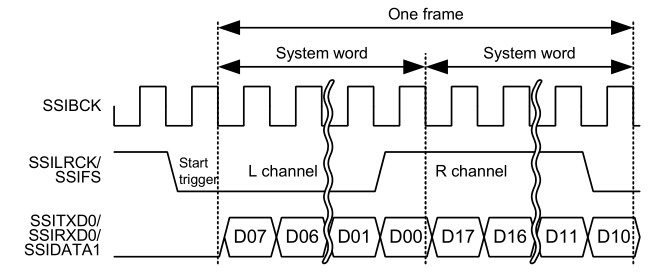
An SSI frame is 2 samples worth of data. The frame boundary (end of previous frame, start of next frame) is on the falling edge of the SSILRCKn signal.
Only uncompressed PCM data is supported.
Data arrays have the following size, alignment, and length based on the "Bit Depth" setting:
| Bit Depth | Array Data Type | Required Alignment | Required Length (bytes) |
|---|---|---|---|
| 8 Bits | 8-bit integer | 1 byte alignment | Multiple of 2 |
| 16 Bits | 16-bit integer | 2 byte alignment | Multiple of 4 |
| 18 Bits | 32-bit integer, right justified | 4 byte alignment | Multiple of 8 |
| 20 Bits | 32-bit integer, right justified | 4 byte alignment | Multiple of 8 |
| 22 Bits | 32-bit integer, right justified | 4 byte alignment | Multiple of 8 |
| 24 Bits | 32-bit integer, right justified | 4 byte alignment | Multiple of 8 |
| 32 Bits | 32-bit integer | 4 byte alignment | Multiple of 8 |
The audio clock is only required for master mode.
The bit clock frequency is the product of the sampling frequency and channels and bits per system word:
bit_clock (Hz) = sampling_frequency (Hz) * channels * system_word_bits
I2S data always has 2 channels.
For example, the bit clock for transmitting 2 channels of 16-bit data (using a 16-bit system word) at 44100 Hz would be:
44100 * 2 * 16 = 1,411,200 Hz
The audio clock frequency is used to generate the bit clock frequency. It must be a multiple of the bit clock frequency. Refer to the Bit Clock Divider configuration for divider options. The input audio clock frequency must be:
audio_clock (Hz) = desired_bit_clock (Hz) * bit_clock_divider
To get a bit clock of 1.4 MHz from an audio clock of 2.8 MHz, select the divider Audio Clock / 2.
The audio clock source can come from:
Developers should be aware of the following limitations when using the SSI:
This is a basic example of minimal use of the SSI in an application.
This is an example of using SSI to stream audio data. This application uses a double buffer to store PCM sine wave data. It starts transmitting in the main loop, then loads the next buffer if it is ready in the callback. If the next buffer is not ready, a flag is set in the callback so the application knows to restart transmission in the main loop.
This example also checks the return code of R_SSI_Write() because R_SSI_Write() can return an error if a transmit overflow occurs before the FIFO is reloaded. If a transmit overflow occurs before the FIFO is reloaded, the SSI will be stopped in the error interrupt, and it cannot be restarted until the I2S_EVENT_IDLE callback is received.
Data Structures | |
| struct | ssi_instance_ctrl_t |
| struct | ssi_extended_cfg_t |
Enumerations | |
| enum | ssi_audio_clock_t |
| enum | ssi_clock_div_t |
| struct ssi_instance_ctrl_t |
Channel instance control block. DO NOT INITIALIZE. Initialization occurs when i2s_api_t::open is called.
| struct ssi_extended_cfg_t |
SSI configuration extension. This extension is optional.
| Data Fields | ||
|---|---|---|
| ssi_audio_clock_t | audio_clock | Audio clock source, default is SSI_AUDIO_CLOCK_EXTERNAL. |
| ssi_clock_div_t | bit_clock_div | Select bit clock division ratio. |
| enum ssi_audio_clock_t |
| enum ssi_clock_div_t |
Bit clock division ratio. Bit clock frequency = audio clock frequency / bit clock division ratio.
| fsp_err_t R_SSI_Open | ( | i2s_ctrl_t *const | p_ctrl, |
| i2s_cfg_t const *const | p_cfg | ||
| ) |
Opens the SSI. Implements i2s_api_t::open.
This function sets this clock divisor and the configurations specified in i2s_cfg_t. It also opens the timer and transfer instances if they are provided.
| FSP_SUCCESS | Ready for I2S communication. |
| FSP_ERR_ASSERTION | The pointer to p_ctrl or p_cfg is null. |
| FSP_ERR_ALREADY_OPEN | The control block has already been opened. |
| FSP_ERR_IP_CHANNEL_NOT_PRESENT | Channel number is not available on this MCU. |
| fsp_err_t R_SSI_Write | ( | i2s_ctrl_t *const | p_ctrl, |
| void const *const | p_src, | ||
| uint32_t const | bytes | ||
| ) |
Writes data buffer to SSI. Implements i2s_api_t::write.
This function resets the transfer if the transfer interface is used, or writes the length of data that fits in the FIFO then stores the remaining write buffer in the control block to be written in the ISR.
Write() cannot be called if another write(), read() or writeRead() operation is in progress. Write can be called when the SSI is idle, or after the I2S_EVENT_TX_EMPTY event.
| FSP_SUCCESS | Write initiated successfully. |
| FSP_ERR_ASSERTION | The pointer to p_ctrl or p_src was null, or bytes requested was 0. |
| FSP_ERR_IN_USE | Another transfer is in progress, data was not written. |
| FSP_ERR_NOT_OPEN | The channel is not opened. |
| FSP_ERR_UNDERFLOW | A transmit underflow error is pending. Wait for the SSI to go idle before resuming communication. |
| fsp_err_t R_SSI_Read | ( | i2s_ctrl_t *const | p_ctrl, |
| void *const | p_dest, | ||
| uint32_t const | bytes | ||
| ) |
Reads data into provided buffer. Implements i2s_api_t::read.
This function resets the transfer if the transfer interface is used, or reads the length of data available in the FIFO then stores the remaining read buffer in the control block to be filled in the ISR.
Read() cannot be called if another write(), read() or writeRead() operation is in progress. Read can be called when the SSI is idle, or after the I2S_EVENT_RX_FULL event.
| FSP_SUCCESS | Read initiated successfully. |
| FSP_ERR_IN_USE | Peripheral is in the wrong mode or not idle. |
| FSP_ERR_ASSERTION | The pointer to p_ctrl or p_dest was null, or bytes requested was 0. |
| FSP_ERR_NOT_OPEN | The channel is not opened. |
| FSP_ERR_OVERFLOW | A receive overflow error is pending. Wait for the SSI to go idle before resuming communication. |
| fsp_err_t R_SSI_WriteRead | ( | i2s_ctrl_t *const | p_ctrl, |
| void const *const | p_src, | ||
| void *const | p_dest, | ||
| uint32_t const | bytes | ||
| ) |
Writes from source buffer and reads data into destination buffer. Implements i2s_api_t::writeRead.
This function calls R_SSI_Write and R_SSI_Read.
writeRead() cannot be called if another write(), read() or writeRead() operation is in progress. writeRead() can be called when the SSI is idle, or after the I2S_EVENT_RX_FULL event.
| FSP_SUCCESS | Write and read initiated successfully. |
| FSP_ERR_IN_USE | Peripheral is in the wrong mode or not idle. |
| FSP_ERR_ASSERTION | An input parameter was invalid. |
| FSP_ERR_NOT_OPEN | The channel is not opened. |
| FSP_ERR_UNDERFLOW | A transmit underflow error is pending. Wait for the SSI to go idle before resuming communication. |
| FSP_ERR_OVERFLOW | A receive overflow error is pending. Wait for the SSI to go idle before resuming communication. |
| fsp_err_t R_SSI_Stop | ( | i2s_ctrl_t *const | p_ctrl | ) |
Stops SSI. Implements i2s_api_t::stop.
This function disables both transmission and reception, and disables any transfer instances used.
The SSI will stop on the next frame boundary. Do not restart SSI until it is idle.
| FSP_SUCCESS | I2S communication stop request issued. |
| FSP_ERR_ASSERTION | The pointer to p_ctrl was null. |
| FSP_ERR_NOT_OPEN | The channel is not opened. |
| fsp_err_t R_SSI_Mute | ( | i2s_ctrl_t *const | p_ctrl, |
| i2s_mute_t const | mute_enable | ||
| ) |
Mutes SSI on the next frame boundary. Implements i2s_api_t::mute.
Data is still written while mute is enabled, but the transmit line outputs zeros.
| FSP_SUCCESS | Transmission is muted. |
| FSP_ERR_ASSERTION | The pointer to p_ctrl was null. |
| FSP_ERR_NOT_OPEN | The channel is not opened. |
| fsp_err_t R_SSI_StatusGet | ( | i2s_ctrl_t *const | p_ctrl, |
| i2s_status_t *const | p_status | ||
| ) |
Gets SSI status and stores it in provided pointer p_status. Implements i2s_api_t::statusGet.
| FSP_SUCCESS | Information stored successfully. |
| FSP_ERR_ASSERTION | The p_instance_ctrl or p_status parameter was null. |
| FSP_ERR_NOT_OPEN | The channel is not opened. |
| fsp_err_t R_SSI_Close | ( | i2s_ctrl_t *const | p_ctrl | ) |
Closes SSI. Implements i2s_api_t::close.
This function powers down the SSI and closes the lower level timer and transfer drivers if they are used.
| FSP_SUCCESS | Device closed successfully. |
| FSP_ERR_ASSERTION | The pointer to p_ctrl was null. |
| FSP_ERR_NOT_OPEN | The channel is not opened. |
| fsp_err_t R_SSI_CallbackSet | ( | i2s_ctrl_t *const | p_api_ctrl, |
| void(*)(i2s_callback_args_t *) | p_callback, | ||
| void *const | p_context, | ||
| i2s_callback_args_t *const | p_callback_memory | ||
| ) |
Updates the user callback and has option of providing memory for callback structure. Implements i2s_api_t::callbackSet
| FSP_SUCCESS | Callback updated successfully. |
| FSP_ERR_ASSERTION | A required pointer is NULL. |
| FSP_ERR_NOT_OPEN | The control block has not been opened. |
| FSP_ERR_NO_CALLBACK_MEMORY | p_callback is non-secure and p_callback_memory is either secure or NULL. |