|
RA Flexible Software Package Documentation
Release v6.5.1
|
|
|
RA Flexible Software Package Documentation
Release v6.5.1
|
|
Driver for the ULPT peripheral on RA MCUs. This module implements the Timer Interface.
The ULPT module has the following features:
RA MCUs can have multiple timer peripherals: the General PWM Timer (GPT) and the Asynchronous General Purpose Timer, and the Ultra Low Power Timer (ULPT). When selecting between them, consider these factors:
| GPT | AGT | ULPT | |
|---|---|---|---|
| Low Power Modes | The GPT can operate in sleep mode. | The AGT can operate in all low power modes (when count source is LOCO or subclock). | The ULPT can operate in all low power up to DSTBYs (when count source is LOCO or subclock). |
| Available Channels | The number of GPT channels is device specific. All currently supported MCUs have at least 7 GPT channels. | All MCUs have 2 AGT channels. | The number of ULPT channels is device specific, 2 is common. |
| Timer Resolution | All MCUs have at least one 32-bit GPT timer. | The AGT timers are 16-bit timers. | The ULPT timers are 32-bit timers. |
| Clock Source | The GPT runs off PCLKD with a configurable divider up to 1024. It can also be configured to count ELC events or external pulses. | The AGT runs off PCLKB, LOCO, or subclock with a configurable divider up to 8 for PCLKB or up to 128 for LOCO or subclock. | The ULPT runs off PCLKB. LOCO, or subclock are count sources with a configurable divider up to 128. |
| Device Group | Devices |
|---|---|
| RA8 | RA8D1, RA8D2, RA8E1, RA8E2, RA8M1, RA8M2, RA8P1, RA8T1, RA8T2 |
| Configuration | Options | Default | Description |
|---|---|---|---|
| Parameter Checking |
| Default (BSP) | If selected code for parameter checking is included in the build. |
| Pin Output Support |
| Disabled | If selected code for outputting a waveform to a pin is included in the build. |
| Pin Input Support |
| Disabled | Enable input support to use ULPTEVin as count source |
| Configuration | Options | Default | Description |
|---|---|---|---|
| General | |||
| Name | Name must be a valid C symbol | g_timer0 | Module name. |
| Channel | Channel number does not exist | 0 | Physical hardware channel. |
| Mode |
| Periodic | Mode selection. Note: One-shot mode is implemented in software. ISR's must be enabled for one shot even if callback is unused. |
| Period | Value must be non-negative | 0x10000 | Specify the timer period based on the selected unit. When the unit is set to 'Raw Counts', setting the period to 0x10000 results in the maximum period at the lowest divisor (fastest timer tick). Set the period to 0x10000 for a free running timer, pulse width measurement or pulse period measurement. Setting the period higher will automatically select a higher divider; the period can be set up to 0x80000 when counting from PCLKB or 0x800000 when counting from LOCO/subclock, which will use a divider of 8 or 128 respectively with the maximum period. If the requested period cannot be achieved, the settings with the largest possible period that is less than or equal to the requested period are used. The theoretical calculated period is printed in a comment in the timer_cfg_t structure. |
| Period Unit |
| Raw Counts | Unit of the period specified above |
| Count Source |
| LOCO | ULPT count source. NOTE: The divisor is calculated automatically based on the selected period. See ulpt_count_source_t documentation for details. |
| Output | |||
| Duty Cycle Percent (only applicable in PWM mode) | Value must be between 0 and 100 | 50 | Specify the timer duty cycle percent. Only used in PWM mode. |
| ULPTOA Output |
| Disabled | Configure Match ULPTOA output. |
| ULPTOB Output |
| Disabled | Configure Match ULPTOB output. |
| ULPTO Output |
| Disabled | Configure Pulse ULPTO output. |
| Input | |||
| Input Filter |
| No Filter | ULPTEVIn filter. Only applies if the count source is ULPTEVIn, event counter mode. The filter requires the signal to be at the same level for 3 successive reads at the specified filter frequency. |
| Enable Pin |
| Enable Function Ignored | ULPTEEn enable edge. Only applies if the count source is ULPTEVIn, event counter mode |
| Trigger Edge |
| Trigger Edge Rising | ULPTEVIn trigger edge. Applies Only applies if the count source is ULPTEVIn, event counter mode. |
| Event Edge |
| Event Edge Rising | Select the ULPTEVin edge. Applies if count input is ULPTEVin. |
| Interrupts | |||
| Callback | Name must be a valid C symbol | NULL | A user callback function. If this callback function is provided, it is called from the interrupt service routine (ISR) each time the timer period elapses. |
| Underflow Interrupt Priority | MCU Specific Options | Timer interrupt priority. | |
The ULPT subsystem is driven by the PCLKB, but countdown is driven LOCO, Subclock, or event input. You can set the clock frequency using the Clocks tab of the RA Configuration editor or by using the CGC Interface at run-time.
This module can use the ULPTO, ULPTOA and ULPTOB pins as output pins for periodic, one-shot, or PWM signals.
For event counting, the input clocking signal must be applied to the ULPTEVIn pin.
The RA Configuration editor will automatically calculate the period count value and source clock divider based on the selected period time, units, and clock speed.
When the selected unit is "Raw counts", the maximum allowed period setting varies depending on the selected clock source:
| Clock source | Maximum period (counts) |
|---|---|
| LOCO/Subclock | 0xFFFFFFFF |
| All other sources | 0xFFFFFFFF |
After starting or stopping the timer, ULPT registers cannot be accessed until the ULPT state is updated after 3 ULPTCLK cycles. If another ULPT function is called before the 3 ULPTCLK period elapses, the function spins waiting for the ULPT state to update. The required wait time after starting or stopping the timer can be determined using the frequency of ULPTCLK, which is derived from timer_cfg_t::source_div and ulpt_extended_cfg_t::count_source.
The application is responsible for ensuring required clocks are started and stable before accessing MCU peripheral registers.
The ULPT can be used to enter snooze mode or to wake the MCU from snooze, software standby, or deep software standby modes when a counter underflow occurs. The compare match A and B events can also be used to wake from software standby or snooze modes.
The ULPT timer does support one-shot mode natively. The interrupt with put the module in the stop state. The callback is only called once in this case. If needed the timer needs to be re-started via the driver call.
The ULPTO toggles each time the counter underflows.
Examples of periodic signals that can be generated by this module are shown below:
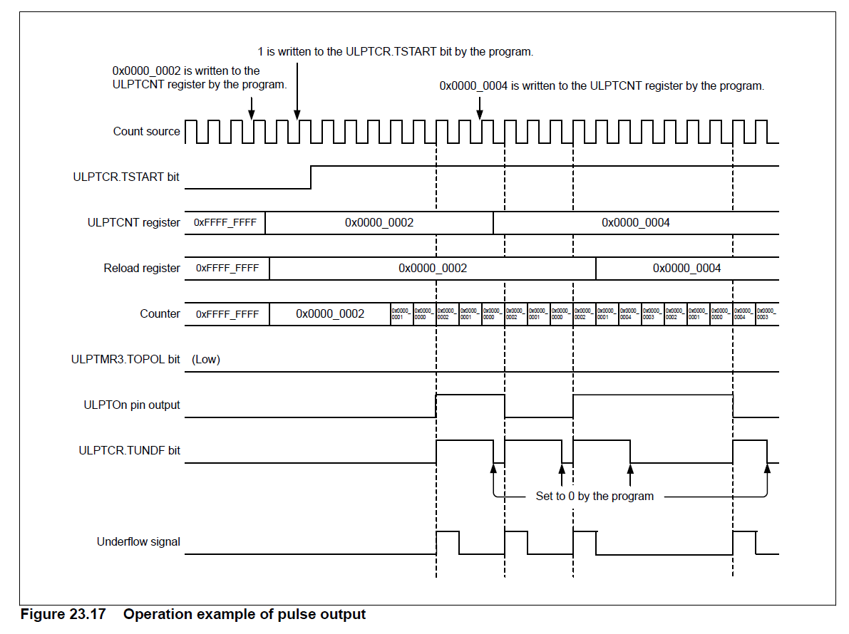
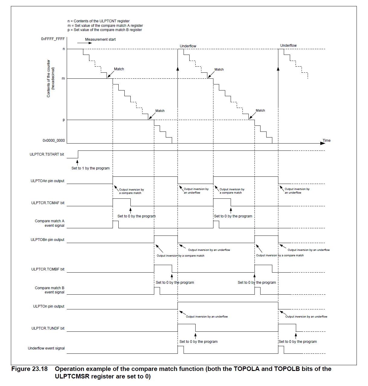
The ULPTOA or ULPTOB pin toggles each time the compare match timer matches the down counter. It also toggles once the underflow occurs in periodic mode. for example setting the ULPT counter to 0x1000, and compare match A to half (0x800) will created a 50% duty cycle output on ULPTOA. Setting ULPTB to a quarter of that (0x400) will create a 25% duty cycle wave. Since the periodic output is actually a PWM output, the time at the stop level is one cycle shorter than the time opposite the stop level for odd period values.
Examples of periodic signals that can be generated by this module are shown below:
The ULPT timer can trigger the start of other peripherals. The Event Link Controller (r_elc) guide provides a list of all available peripherals.
This is a basic example of minimal use of the ULPT in an application.
This is an example of a timer callback.
To use the ULPT as a free running counter, select periodic mode and set the the Period to 0xFFFFFFFF.
This an example of updating the period.
This an example of updating the duty cycle.
Data Structures | |
| struct | ulpt_instance_ctrl_t |
| struct | ulpt_extended_cfg_t |
Enumerations | |
| enum | ulpt_clock_t |
| enum | ulpt_enable_function_t |
| enum | ulpt_trigger_edge_t |
| enum | ulpt_event_pin_t |
| enum | ulpt_output_pin_t |
| enum | ulpt_pulse_pin_cfg_t |
| enum | ulpt_match_pin_cfg_t |
| enum | ulpt_ulptevi_filter_t |
| struct ulpt_instance_ctrl_t |
Channel control block. DO NOT INITIALIZE. Initialization occurs when timer_api_t::open is called.
| struct ulpt_extended_cfg_t |
Optional ULPT extension data structure.
| Data Fields | ||
|---|---|---|
| ulpt_clock_t | count_source | ULPT channel clock source. |
| ulpt_ulptevi_filter_t | ulptevi_filter | Input filter for ULTPEVI. |
| ulpt_enable_function_t | enable_function | Counter function when ULPTEE is valid. |
| ulpt_trigger_edge_t | trigger_edge | Enable trigger edge (start and restart functions only). |
| ulpt_event_pin_t | event_pin | Event pin (event counting only). |
| ulpt_pulse_pin_cfg_t | ulpto | Pulse output pin. |
| union ulpt_extended_cfg_t | __unnamed__ | |
| enum ulpt_clock_t |
Counter mode for event enable.
| enum ulpt_trigger_edge_t |
Enable signal trigger edge for start and restart functions.
| enum ulpt_event_pin_t |
| enum ulpt_output_pin_t |
Output pins, used to select which duty cycle to update in R_ULPT_DutyCycleSet().
| Enumerator | |
|---|---|
| ULPT_OUTPUT_PIN_ULPTOA | Compare match A output. |
| ULPT_OUTPUT_PIN_ULPTOB | Compare match B output. |
| enum ulpt_pulse_pin_cfg_t |
| enum ulpt_match_pin_cfg_t |
Input filter, applied to ULPTEVI in event counter mode. The filter requires the signal to be at the same level for 3 successive reads at the specified filter frequency.
| Enumerator | |
|---|---|
| ULPT_ULPTEVI_FILTER_NONE | No filter. |
| ULPT_ULPTEVI_FILTER_PCLKB | Filter at PCLKB. |
| ULPT_ULPTEVI_FILTER_PCLKB_DIV_8 | Filter at PCLKB / 8. |
| ULPT_ULPTEVI_FILTER_PCLKB_DIV_32 | Filter at PCLKB / 32. |
| fsp_err_t R_ULPT_Open | ( | timer_ctrl_t *const | p_ctrl, |
| timer_cfg_t const *const | p_cfg | ||
| ) |
Initializes the ULPT module instance. Implements timer_api_t::open.
The ULPT implementation of the general timer can accept an optional ulpt_extended_cfg_t extension parameter. For ULPT, the extension specifies the clock to be used as timer source and the output pin configurations. If the extension parameter is not specified (NULL), the default clock LOCO is used and the output pins are disabled.
Example:
| FSP_SUCCESS | Initialization was successful and timer has started. |
| FSP_ERR_ASSERTION | A required input pointer is NULL or the period is not in the valid range of 1 to 0xFFFF. |
| FSP_ERR_ALREADY_OPEN | R_ULPT_Open has already been called for this p_ctrl. |
| FSP_ERR_IRQ_BSP_DISABLED | A required interrupt has not been enabled in the vector table. |
| FSP_ERR_IP_CHANNEL_NOT_PRESENT | Requested channel number is not available on ULPT. |
| fsp_err_t R_ULPT_Start | ( | timer_ctrl_t *const | p_ctrl | ) |
Starts timer. Implements timer_api_t::start.
Example:
| FSP_SUCCESS | Timer started. |
| FSP_ERR_ASSERTION | p_ctrl is null. |
| FSP_ERR_NOT_OPEN | The instance control structure is not opened. |
| fsp_err_t R_ULPT_Stop | ( | timer_ctrl_t *const | p_ctrl | ) |
Stops the timer. Implements timer_api_t::stop.
Example:
| FSP_SUCCESS | Timer stopped. |
| FSP_ERR_ASSERTION | p_ctrl was NULL. |
| FSP_ERR_NOT_OPEN | The instance control structure is not opened. |
| fsp_err_t R_ULPT_Reset | ( | timer_ctrl_t *const | p_ctrl | ) |
Resets the counter value to the period minus one. Implements timer_api_t::reset.
| FSP_SUCCESS | Counter reset. |
| FSP_ERR_ASSERTION | p_ctrl is NULL |
| FSP_ERR_NOT_OPEN | The instance control structure is not opened. |
| fsp_err_t R_ULPT_Enable | ( | timer_ctrl_t *const | p_ctrl | ) |
Enables external event triggers that start, stop, clear, or capture the counter. Implements timer_api_t::enable.
Example:
| FSP_SUCCESS | External events successfully enabled. |
| FSP_ERR_ASSERTION | p_ctrl was NULL. |
| FSP_ERR_NOT_OPEN | The instance is not opened. |
| fsp_err_t R_ULPT_Disable | ( | timer_ctrl_t *const | p_ctrl | ) |
Disables external event triggers that start, stop, clear, or capture the counter. Implements timer_api_t::disable.
Example:
| FSP_SUCCESS | External events successfully disabled. |
| FSP_ERR_ASSERTION | p_ctrl was NULL. |
| FSP_ERR_NOT_OPEN | The instance is not opened. |
| fsp_err_t R_ULPT_PeriodSet | ( | timer_ctrl_t *const | p_ctrl, |
| uint32_t const | period_counts | ||
| ) |
Updates period. The new period is updated immediately and the counter is reset to the maximum value. Implements timer_api_t::periodSet.
Example:
| FSP_SUCCESS | Period value updated. |
| FSP_ERR_ASSERTION | A required pointer was NULL, or the period was not in the valid range of 1 to 0xFFFF. |
| FSP_ERR_NOT_OPEN | The instance control structure is not opened. |
| fsp_err_t R_ULPT_DutyCycleSet | ( | timer_ctrl_t *const | p_ctrl, |
| uint32_t const | duty_cycle_counts, | ||
| uint32_t const | pin | ||
| ) |
Updates duty cycle. If the timer is counting, the new duty cycle is reflected after the next counter underflow. Implements timer_api_t::dutyCycleSet.
Example:
| FSP_SUCCESS | Duty cycle updated. |
| FSP_ERR_ASSERTION | A required pointer was NULL, or the pin was not ULPT_ULPTO_ULPTOA or ULPT_ULPTO_ULPTOB. |
| FSP_ERR_INVALID_ARGUMENT | Duty cycle was not in the valid range of 0 to period (counts) - 1 |
| FSP_ERR_NOT_OPEN | The instance control structure is not opened. |
| FSP_ERR_UNSUPPORTED | ULPT_CFG_OUTPUT_SUPPORT_ENABLE is 0. |
| fsp_err_t R_ULPT_CompareMatchSet | ( | timer_ctrl_t *const | p_ctrl, |
| uint32_t const | compare_match_value, | ||
| timer_compare_match_t const | match_channel | ||
| ) |
Placeholder for unsupported compareMatch function. Implements timer_api_t::compareMatchSet.
| FSP_ERR_UNSUPPORTED | ULPT compare match is not supported. |
| fsp_err_t R_ULPT_InfoGet | ( | timer_ctrl_t *const | p_ctrl, |
| timer_info_t *const | p_info | ||
| ) |
Gets timer information and store it in provided pointer p_info. Implements timer_api_t::infoGet.
Example:
| FSP_SUCCESS | Period, count direction, and frequency stored in p_info. |
| FSP_ERR_ASSERTION | A required pointer is NULL. |
| FSP_ERR_NOT_OPEN | The instance control structure is not opened. |
| fsp_err_t R_ULPT_StatusGet | ( | timer_ctrl_t *const | p_ctrl, |
| timer_status_t *const | p_status | ||
| ) |
Retrieves the current state and counter value stores them in p_status. Implements timer_api_t::statusGet.
Example:
| FSP_SUCCESS | Current status and counter value provided in p_status. |
| FSP_ERR_ASSERTION | A required pointer is NULL. |
| FSP_ERR_NOT_OPEN | The instance control structure is not opened. |
| fsp_err_t R_ULPT_CallbackSet | ( | timer_ctrl_t *const | p_api_ctrl, |
| void(*)(timer_callback_args_t *) | p_callback, | ||
| void *const | p_context, | ||
| timer_callback_args_t *const | p_callback_memory | ||
| ) |
Updates the user callback with the option to provide memory for the callback argument structure. Implements timer_api_t::callbackSet.
| FSP_SUCCESS | Callback updated successfully. |
| FSP_ERR_ASSERTION | A required pointer is NULL. |
| FSP_ERR_NOT_OPEN | The control block has not been opened. |
| FSP_ERR_NO_CALLBACK_MEMORY | p_callback is non-secure and p_callback_memory is either secure or NULL. |
| fsp_err_t R_ULPT_Close | ( | timer_ctrl_t *const | p_ctrl | ) |
Stops counter, disables interrupts, disables output pins, and clears internal driver data. Implements timer_api_t::close.
| FSP_SUCCESS | Timer closed. |
| FSP_ERR_ASSERTION | p_ctrl is NULL. |
| FSP_ERR_NOT_OPEN | The instance control structure is not opened. |