|
RA Flexible Software Package Documentation
Release v6.5.1
|
|
|
RA Flexible Software Package Documentation
Release v6.5.1
|
|
Driver for the GPT32 and GPT16 peripherals on RA MCUs. This module implements the Timer Interface.
The GPT module can be used to count events, measure external input signals, generate a periodic interrupt, or output a periodic or PWM signal to a GTIOC pin.
This module supports the GPT peripherals GPT32EH, GPT32E, GPT32, and GPT16. GPT16 is a 16-bit timer. The other peripherals (GPT32EH, GPT32E, and GPT32) are 32-bit timers. The 32-bit timers are all treated the same in this module from the API perspective.
The GPT module has the following features:
RA MCUs have two timer peripherals: the General PWM Timer (GPT) and the Asynchronous General Purpose Timer (AGT). When selecting between them, consider these factors:
| GPT | AGT | |
|---|---|---|
| Low Power Modes | The GPT can operate in sleep mode. | The AGT can operate in all low power modes. |
| Available Channels | The number of GPT channels is device specific. All currently supported MCUs have at least 7 GPT channels. | All MCUs have 2 AGT channels. |
| Timer Resolution | All MCUs have at least one 32-bit GPT timer. | The AGT timers are 16-bit timers. |
| Clock Source | The GPT runs off PCLKD with a configurable divider up to 1024. It can also be configured to count ELC events or external pulses. | The AGT runs off PCLKB, LOCO, or subclock. |
| Device Group | Devices |
|---|---|
| RA2 | RA2A1, RA2A2, RA2E1, RA2E2, RA2E3, RA2L1, RA2L2, RA2T1 |
| RA4 | RA4C1, RA4E1, RA4E2, RA4L1, RA4M1, RA4M2, RA4M3, RA4T1, RA4W1 |
| RA6 | RA6E1, RA6E2, RA6M1, RA6M2, RA6M3, RA6M4, RA6M5, RA6T1, RA6T2, RA6T3 |
| RA8 | RA8D1, RA8D2, RA8E1, RA8E2, RA8M1, RA8M2, RA8P1, RA8T1, RA8T2 |
| Configuration | Options | Default | Description |
|---|---|---|---|
| Parameter Checking |
| Default (BSP) | If selected code for parameter checking is included in the build. |
| Pin Output Support |
| Disabled | Enables or disables support for outputting PWM waveforms on GTIOCx pins. The "Enabled with Extra Features" option enables support for Triangle wave modes and also enables the features located in the "Extra Features" section of each module instance. |
| Write Protect Enable |
| Disabled | If selected write protection is applied to all GPT channels. |
| Configuration | Options | Default | Description |
|---|---|---|---|
| General | |||
| General > Compare Match | |||
| General > Compare Match > Compare Match A | |||
| Status |
| Disabled | |
| Compare match value | Value must be greater than 0 and less than or equal to 0x40000000000 | 0x10000 | Specify the value of compare match A in units matching those selected in the 'Period Unit' property. |
| General > Compare Match > Compare Match B | |||
| Status |
| Disabled | |
| Compare match value | Value must be greater than 0 and less than or equal to 0x40000000000 | 0x10000 | Specify the value of compare match B in units matching those selected in the 'Period Unit' property. |
| General > Compare Match > Compare Match C | |||
| Status |
| Disabled | |
| Compare match value | Value must be greater than 0 and less than or equal to 0x40000000000 | 0x10000 | Specify the value of compare match C in units matching those selected in the 'Period Unit' property. |
| General > Compare Match > Compare Match D | |||
| Status |
| Disabled | |
| Compare match value | Value must be greater than 0 and less than or equal to 0x40000000000 | 0x10000 | Specify the value of compare match D in units matching those selected in the 'Period Unit' property. |
| General > Compare Match > Compare Match E | |||
| Status |
| Disabled | |
| Compare match value | Value must be greater than 0 and less than or equal to 0x40000000000 | 0x10000 | Specify the value of compare match E in units matching those selected in the 'Period Unit' property. |
| General > Compare Match > Compare Match F | |||
| Status |
| Disabled | |
| Compare match value | Value must be greater than 0 and less than or equal to 0x40000000000 | 0x10000 | Specify the value of compare match F in units matching those selected in the 'Period Unit' property. |
| Name | Name must be a valid C symbol | g_timer0 | Module name. |
| Channel | Enter the supported Channel number | 0 | Specify the hardware channel. |
| Mode |
| Periodic | Mode selection. Periodic: Generates periodic interrupts or square waves. One-shot: Generate a single interrupt or a pulse wave. Note: One-shot mode is implemented in software. ISRs must be enabled for one-shot even if callback is unused. One-Shot Pulse: Counter performs saw-wave operation with fixed buffer operation. Saw-wave PWM: Generates basic saw-wave PWM waveforms. Triangle-wave PWM (symmetric, Mode 1): Generates symmetric PWM waveforms with duty cycle determined by compare match set with 32-bit transfer during a crest event and updated at the next trough with single or double buffer operation. Triangle-wave PWM (asymmetric, Mode 2): Generates asymmetric PWM waveforms with duty cycle determined by compare match set with 32-bit transfer during a crest/trough event and updated at the next trough/crest. Triangle-wave PWM (asymmetric, Mode 3): Generates PWM waveforms with duty cycle determined by compare match set with 64-bit transfer during a crest interrupt and updated at the next trough with fixed buffer operation. |
| Period | Value must be a non-negative integer less than or equal to 0x40000000000 | 0x10000 | Specify the timer period in units selected below. Set the period to 0x100000000 (32-bit) or 0x10000 (16-bit) raw counts for a free running timer or an input capture configuration. The period can be set up to 0x40000000000 (32-bit) or 0x4000000 (16-bit) which will use a divider of 1024 with the maximum period. If the requested period cannot be achieved, the settings with the largest possible period that is less than or equal to the requested period are used. The theoretical calculated period is printed in a comment in the generated timer_cfg_t structure. |
| Period Unit |
| Raw Counts | Unit of the period specified above |
| Output | |||
| Output > Custom Waveform | |||
| Output > Custom Waveform > GTIOA | |||
| Initial Output Level |
| Pin Level Low | Set the initial output level of GTIOCxA. |
| Cycle End Output Level |
| Pin Level Retain | Set the output level of GTIOCxA at cycle end. |
| Compare Match Output Level |
| Pin Level Retain | Set the output level of GTIOCxA at compare match. |
| Retain Output Level at Count Stop |
| Disabled | Retain the current GTIOxA output level when counting is stopped. |
| Output > Custom Waveform > GTIOB | |||
| Initial Output Level |
| Pin Level Low | Set the initial output level of GTIOCxB. |
| Cycle End Output Level |
| Pin Level Retain | Set the output level of GTIOCxB at cycle end. |
| Compare Match Output Level |
| Pin Level Retain | Set the output level of GTIOCxB at compare match. |
| Retain Output Level at Count Stop |
| Disabled | Retain the current GTIOxB output level when counting is stopped. |
| Custom Waveform Enable |
| Disabled | Enable custom waveform configuration. |
| Duty Cycle Percent (only applicable in PWM mode) | Value must be between 0 and 100 | 50 | Specify the timer duty cycle percent. Only used in PWM mode. |
| GTIOCA Output Enabled |
| False | Enable the output of GTIOCA on a pin. |
| GTIOCA Stop Level |
| Pin Level Low | Select the behavior of the output pin when the timer is stopped. |
| GTIOCB Output Enabled |
| False | Enable the output of GTIOCB on a pin. |
| GTIOCB Stop Level |
| Pin Level Low | Select the behavior of the output pin when the timer is stopped. |
| Input | |||
| Count Up Source | MCU Specific Options | Select external source that will increment the counter. If any count up source is selected, the timer will count the external sources only. It will not count PCLKD cycles. | |
| Count Down Source | MCU Specific Options | Select external source that will decrement the counter. If any count down source is selected, the timer will count the external sources only. It will not count PCLKD cycles. | |
| Start Source | MCU Specific Options | Select external source that will start the timer. For pulse width measurement, set the Start Source and the Clear Source to the trigger edge (the edge to start the measurement), and set the Stop Source and Capture Source (either A or B) to the opposite edge (the edge to stop the measurement). For pulse period measurement, set the Start Source, the Clear Source, and the Capture Source (either A or B) to the trigger edge (the edge to start the measurement). | |
| Stop Source | MCU Specific Options | Select external source that will stop the timer. | |
| Clear Source | MCU Specific Options | Select external source that will clear the timer. | |
| Capture A Source | MCU Specific Options | Select external source that will trigger a capture A event. | |
| Capture B Source | MCU Specific Options | Select external source that will trigger a capture B event. | |
| Noise Filter A Sampling Clock Select |
| No Filter | Select the input filter for GTIOCA. |
| Noise Filter B Sampling Clock Select |
| No Filter | Select the input filter for GTIOCB. |
| Pin Polarity | |||
| GTIOCnA Polarity |
| Normal | Input/output polarity control for GTIOCnA pin. |
| GTIOCnB Polarity |
| Normal | Input/output polarity control for GTIOCnB pin. |
| Interrupts | |||
| Callback | Name must be a valid C symbol | NULL | A user callback function can be specified here. If this callback function is provided, it will be called from the interrupt service routine (ISR) each time the timer period elapses |
| Overflow/Crest Interrupt Priority | MCU Specific Options | Select the overflow interrupt priority. This is the crest interrupt for triangle-wave PWM. | |
| Capture/Compare match A Interrupt Priority | MCU Specific Options | Select the interrupt priority for Capture/Compare match A. | |
| Capture/Compare match B Interrupt Priority | MCU Specific Options | Select the interrupt priority for Capture/Compare match B. | |
| Compare Match C Interrupt Priority | MCU Specific Options | Select the interrupt priority for Compare match C. | |
| Compare Match D Interrupt Priority | MCU Specific Options | Select the interrupt priority for Compare match D. | |
| Compare Match E Interrupt Priority | MCU Specific Options | Select the interrupt priority for Compare match E. | |
| Compare Match F Interrupt Priority | MCU Specific Options | Select the interrupt priority for Compare match F. | |
| Underflow/Trough Interrupt Priority | MCU Specific Options | Select the interrupt priority for the trough interrupt (triangle-wave PWM only). | |
| Extra Features | |||
| Extra Features > Output Disable | |||
| POEG Link | MCU Specific Options | Select which POEG to link this GPT channel to. | |
| Output Disable POEG Trigger |
| Select which errors send an output disable trigger to POEG. Dead time error is only available GPT channels that have GTINTAD.GRPDTE. | |
| GTIOCA Disable Setting |
| Disable Prohibited | Select the disable setting for GTIOCA. |
| GTIOCB Disable Setting |
| Disable Prohibited | Select the disable setting for GTIOCB. |
| Extra Features > ADC Trigger | |||
| Start Event Trigger (Channels with GTINTAD only) |
| Select which A/D converter start request interrupts to generate and at which point in the cycle to generate them. | |
| ADC A Compare Match (Raw Counts) | Must be a valid non-negative integer with a maximum configurable value of 4294967295 (0xffffffff). | 0 | Select the compare match value that generates a GPTn AD TRIG A event. |
| ADC B Compare Match (Raw Counts) | Must be a valid non-negative integer with a maximum configurable value of 4294967295 (0xffffffff). | 0 | Select the compare match value that generates a GPTn AD TRIG B event. |
| Extra Features > Dead Time (Value range varies with Channel) | |||
| Dead Time Count Up (Raw Counts) | Must be a valid non-negative integer with a maximum configurable value of 4294967295 (0xffffffff). | 0 | Select the dead time to apply during up counting. This value also applies during down counting for channels that do not have GTDVD. The dead time count up value can be set up to 0xffffffff (32-bit) or 0xffff (16-bit). |
| Dead Time Count Down (Raw Counts) (Channels with GTDVD only) | Must be a valid non-negative integer with a maximum configurable value of 4294967295 (0xffffffff). | 0 | Select the dead time to apply during down counting. The dead time count down value can be set up to 0xffffffff (32-bit) or 0xffff (16-bit). |
| Extra Features > Interrupt Skipping (Channels with GTITC only) | |||
| Interrupt to Count |
| None | Select the count source for interrupt skipping. The interrupt skip counter increments after each source event. All crest/overflow and trough/underflow interrupts are skipped when the interrupt skip counter is non-zero. |
| Interrupt Skip Count |
| 0 | Select the number of interrupts to skip. |
| Skip ADC Events |
| None | Select ADC events to suppress when the interrupt skip count is not zero. |
| Extra Features |
| Disabled | Select whether to enable extra features on this channel. |
The GPT clock is based on the PCLKD frequency. You can set the PCLKD frequency using the Clocks tab of the RA Configuration editor or by using the CGC Interface at run-time.
This module can use GTETRGA, GTETRGB, GTETRGC, GTETRGD, GTIOCA and GTIOCB pins as count sources.
This module can use GTIOCA and GTIOCB pins as output pins for periodic or PWM signals.
This module can use GTIOCA and GTIOCB as input pins to measure input signals.
The RA Configuration editor will automatically calculate the period count value and source clock divider based on the selected period time, units and clock speed.
When the selected period unit is "Raw counts", the maximum period setting is 0x40000000000 on a 32-bit timer or 0x4000000 on a 16-bit timer. This will configure the timer with the maximum period and a count clock divisor of 1024.
The period and duty cycle are updated after the next counter overflow after calling R_GPT_PeriodSet() or R_GPT_DutyCycleSet(). To force them to update before the next counter overflow, call R_GPT_Reset() while the counter is running.
The GPT timer does not support one-shot mode natively. One-shot mode is achieved by stopping the timer in the interrupt service routine before the callback is called. If the interrupt is not serviced before the timer period expires again, the timer generates more than one event. The callback is only called once in this case, but multiple events may be generated if the timer is linked to the Transfer (r_dtc).
The output waveform in one-shot mode is one PCLKD cycle less than the configured period. The configured period must be at least 2 counts to generate an output pulse.
Examples of one-shot signals that can be generated by this module are shown below:
The one-shot pulse mode is an asymmetric PWM mode that provides more control over the rising and falling edges of the output. The user provides a period and initial output level and controls the signal by specifying compare match values for the leading and trailing edges each period.
Examples of PWM signals that can be generated by this module are shown below. The leading and trailing edge match values can be modified using R_GPT_DutyCycleSet() in the overflow interrupt.
If dead time is enabled only match values for GTIOCnA need to be set; the match values for GTIOCnB will be automatically configured in hardware.
The GTIOC pin toggles twice each time the timer expires in periodic mode. This is achieved by defining a PWM wave at a 50 percent duty cycle so that the period of the resulting square wave (from rising edge to rising edge) matches the period of the GPT timer. Since the periodic output is actually a PWM output, the time at the stop level is one cycle shorter than the time opposite the stop level for odd period values.
Examples of periodic signals that can be generated by this module are shown below:
The PWM output signal is high at the beginning of the cycle and low at the end of the cycle.
Examples of PWM signals that can be generated by this module are shown below:
Examples of PWM signals that can be generated by this module are shown below. The duty_cycle_counts can be modified using R_GPT_DutyCycleSet() in the crest interrupt and updated at the following trough for symmetric PWM or modified in both the crest/trough interrupts and updated at the following trough/crest for asymmetric PWM.
On select MCUs, an additional PWM output delay circuit can be configured in order to fine tune the rising and falling edge delays in increments of 1/32 times the period of the GPT core clock. The PWM output delay function must be configured prior to initializing the GPT channels using R_GPT_PwmOutputDelayInitialize.
Write_Interval[ns] = Period_of_PCLKA [ns] × 6 + Period_of_GPTCLK [ns] × 4).Event counting can be done by selecting up or down counting sources from GTETRG pins, ELC events, or GTIOC pins. In event counting mode, the GPT counter is not affected by PCLKD.
If the capture edge occurs before the start edge in pulse measurement, the first capture is invalid (0).
The GPT timer can be configured to stop, start, clear, count up, or count down when a GTETRG rising or falling edge occurs.
The GPT timer can be configured to stop, start, clear, count up, or count down when an ELC event occurs.
The GPT timer can trigger the start of other peripherals. The Event Link Controller (r_elc) guide provides a list of all available peripherals.
R_GPT_Enable() must be called when external sources are used for start, stop, clear, or capture.
In Periodic mode, if pin output support is enabled with the Compare Match feature, the output signal is no longer a default 50% duty cycle square wave. Instead, the duty cycle of the PWM waveform is determined by the configured compare match value.
In One-Shot mode, Overflow event must be enabled when using Compare match feature. The interrupt progress of Compare match in One-Shot mode is: CMP_1 -> CMP_2 -> ... -> OVF. The Overflow isr will stop the timer counter at the end of period so all Compare match events will not occur again.
Additionally, the priorities of Overflow and Compare match events in One-shot mode must be equal to ensure the expected order of interrupt occurrence.
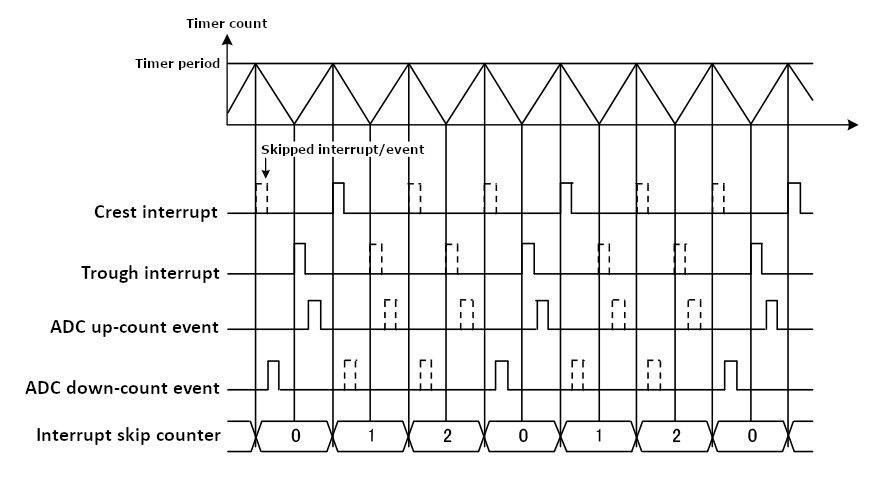
When an interrupt skipping source is selected a hardware counter will increment each time the selected event occurs. Each interrupt past the first (up to the specified skip count) will be suppressed. If ADC events are selected for skipping they will also be suppressed except during the timer period leading to the selected interrupt skipping event (see below diagram).
By using the Custom Waveform option the output pins can be made to output complementary waveforms. To ensure these waveforms stay in sync, the duty cycle for both pins can be set simultaneously by calling R_GPT_DutyCycleSet once with a pin parameter of GPT_IO_PIN_GTIOCA_AND_GTIOCB.
Developers should be aware of the following limitations when using GPT:
This is a basic example of minimal use of the GPT in an application.
This is an example of a timer callback.
To use the GPT as a free running counter, select periodic mode and set the the Period to 0xFFFFFFFF for a 32-bit timer or 0xFFFF for a 16-bit timer.
This is an example of using the GPT to capture pulse width or pulse period measurements.
This an example of updating the period.
This an example of updating the duty cycle.
This is an example of using the GPT to start the ADC at a configurable A/D converter compare match value.
This example demonstrates the configuration and use of one-shot pulse mode with GPT timer.
This example demonstrates the configuration and use of compare match with GPT timer.
Data Structures | |
| struct | gpt_output_pin_t |
| struct | gpt_gtior_setting_t |
| struct | gpt_instance_ctrl_t |
| struct | gpt_extended_pwm_cfg_t |
| struct | gpt_extended_cfg_t |
Enumerations | |
| enum | gpt_io_pin_t |
| enum | gpt_buffer_force_push |
| enum | gpt_pin_level_t |
| enum | gpt_source_t |
| enum | gpt_capture_filter_t |
| enum | gpt_adc_trigger_t |
| enum | gpt_poeg_link_t |
| enum | gpt_output_disable_t |
| enum | gpt_gtioc_disable_t |
| enum | gpt_adc_compare_match_t |
| enum | gpt_interrupt_skip_source_t |
| enum | gpt_interrupt_skip_count_t |
| enum | gpt_interrupt_skip_adc_t |
| enum | gpt_pwm_output_delay_setting_t |
| enum | gpt_pwm_output_delay_edge_t |
| enum | gpt_gtioc_polarity_t |
| struct gpt_output_pin_t |
Configurations for output pins.
| Data Fields | ||
|---|---|---|
| bool | output_enabled | Set to true to enable output, false to disable output. |
| gpt_pin_level_t | stop_level | Select a stop level from gpt_pin_level_t. |
| struct gpt_gtior_setting_t |
Custom GTIOR settings used for configuring GTIOCxA and GTIOCxB pins.
| struct gpt_instance_ctrl_t |
Channel control block. DO NOT INITIALIZE. Initialization occurs when timer_api_t::open is called.
| struct gpt_extended_pwm_cfg_t |
GPT extension for advanced PWM features.
| Data Fields | ||
|---|---|---|
| uint8_t | trough_ipl | Trough interrupt priority. |
| IRQn_Type | trough_irq | Trough interrupt. |
| gpt_poeg_link_t | poeg_link | Select which POEG channel controls output disable for this GPT channel. |
| gpt_output_disable_t | output_disable | Select which trigger sources request output disable from POEG. |
| gpt_adc_trigger_t | adc_trigger | Select trigger sources to start A/D conversion. |
| uint32_t | dead_time_count_up | Set a dead time value for counting up. |
| uint32_t | dead_time_count_down | Set a dead time value for counting down (available on GPT32E and GPT32EH only) |
| uint32_t | adc_a_compare_match | Select the compare match value used to trigger an A/D conversion start request using ELC_EVENT_GPT<channel>_AD_TRIG_A. |
| uint32_t | adc_b_compare_match | Select the compare match value used to trigger an A/D conversion start request using ELC_EVENT_GPT<channel>_AD_TRIG_B. |
| gpt_interrupt_skip_source_t | interrupt_skip_source | Interrupt source to count for interrupt skipping. |
| gpt_interrupt_skip_count_t | interrupt_skip_count | Number of interrupts to skip between events. |
| gpt_interrupt_skip_adc_t | interrupt_skip_adc | ADC events to skip when interrupt skipping is enabled. |
| gpt_gtioc_disable_t | gtioca_disable_setting | Select how to configure GTIOCA when output is disabled. |
| gpt_gtioc_disable_t | gtiocb_disable_setting | Select how to configure GTIOCB when output is disabled. |
| struct gpt_extended_cfg_t |
GPT extension configures the output pins for GPT.
| Data Fields | ||
|---|---|---|
| gpt_output_pin_t | gtioca | Configuration for GPT I/O pin A. |
| gpt_output_pin_t | gtiocb | Configuration for GPT I/O pin B. |
| gpt_source_t | start_source | Event sources that trigger the timer to start. |
| gpt_source_t | stop_source | Event sources that trigger the timer to stop. |
| gpt_source_t | clear_source | Event sources that trigger the timer to clear. |
| gpt_source_t | capture_a_source | Event sources that trigger capture of GTIOCA. |
| gpt_source_t | capture_b_source | Event sources that trigger capture of GTIOCB. |
| gpt_source_t | count_up_source |
Event sources that trigger a single up count. If GPT_SOURCE_NONE is selected for both count_up_source and count_down_source, then the timer count source is PCLK. |
| gpt_source_t | count_down_source |
Event sources that trigger a single down count. If GPT_SOURCE_NONE is selected for both count_up_source and count_down_source, then the timer count source is PCLK. |
| gpt_capture_filter_t | capture_filter_gtioca | |
| gpt_capture_filter_t | capture_filter_gtiocb | |
| uint8_t | capture_a_ipl | Capture/Compare match A interrupt priority. |
| uint8_t | capture_b_ipl | Capture/Compare match B interrupt priority. |
| uint8_t | compare_match_c_ipl | Compare match C interrupt priority. |
| uint8_t | compare_match_d_ipl | Compare match D interrupt priority. |
| uint8_t | compare_match_e_ipl | Compare match E interrupt priority. |
| uint8_t | compare_match_f_ipl | Compare match F interrupt priority. |
| IRQn_Type | capture_a_irq | Capture/Compare match A interrupt. |
| IRQn_Type | capture_b_irq | Capture/Compare match B interrupt. |
| IRQn_Type | compare_match_c_irq | Compare match C interrupt. |
| IRQn_Type | compare_match_d_irq | Compare match D interrupt. |
| IRQn_Type | compare_match_e_irq | Compare match E interrupt. |
| IRQn_Type | compare_match_f_irq | Compare match F interrupt. |
| uint32_t | compare_match_value[6] | Storing compare match value for channels. |
| uint8_t | compare_match_status | Storing the compare match registers status. |
| gpt_extended_pwm_cfg_t const * | p_pwm_cfg | Advanced PWM features, optional. |
| gpt_gtior_setting_t | gtior_setting | Custom GTIOR settings used for configuring GTIOCxA and GTIOCxB pins. |
| gpt_gtioc_polarity_t | gtioca_polarity | Polarity control for GTIOCxA input/output pin. |
| gpt_gtioc_polarity_t | gtiocb_polarity | Polarity control for GTIOCxB input/output pin. |
| enum gpt_io_pin_t |
Input/Output pins, used to select which duty cycle to update in R_GPT_DutyCycleSet().
| Enumerator | |
|---|---|
| GPT_IO_PIN_GTIOCA | GTIOCA. |
| GPT_IO_PIN_GTIOCB | GTIOCB. |
| GPT_IO_PIN_GTIOCA_AND_GTIOCB | GTIOCA and GTIOCB. |
| GPT_IO_PIN_TROUGH | Used in R_GPT_DutyCycleSet when Triangle-wave PWM Mode 3 is selected. |
| GPT_IO_PIN_CREST | Used in R_GPT_DutyCycleSet when Triangle-wave PWM Mode 3 is selected. |
| GPT_IO_PIN_ONE_SHOT_LEADING_EDGE | Used in R_GPT_DutyCycleSet to set GTCCRC and GTCCRE registers when One-Shot Pulse mode is selected. |
| GPT_IO_PIN_ONE_SHOT_TRAILING_EDGE | Used in R_GPT_DutyCycleSet to set GTCCRD and GTCCRF registers when One-Shot Pulse mode is selected. |
Forced buffer push operation used in One-Sot Pulse mode with R_GPT_DutyCycleSet().
| Enumerator | |
|---|---|
| GPT_BUFFER_FORCE_PUSH | Used in R_GPT_DutyCycleSet to force push the data from GTCCRn registers to temporary buffer A or B when One-Shot Pulse mode is selected. |
| enum gpt_pin_level_t |
| enum gpt_source_t |
Sources can be used to start the timer, stop the timer, count up, or count down. These enumerations represent a bitmask. Multiple sources can be ORed together.
| enum gpt_capture_filter_t |
Input capture signal noise filter (debounce) setting. Only available for input signals GTIOCxA and GTIOCxB. The noise filter samples the external signal at intervals of the PCLK divided by one of the values. When 3 consecutive samples are at the same level (high or low), then that level is passed on as the observed state of the signal. See "Noise Filter Function" in the hardware manual, GPT section.
| enum gpt_adc_trigger_t |
Trigger options to start A/D conversion.
| Enumerator | |
|---|---|
| GPT_ADC_TRIGGER_NONE | None - no output disable request. |
| GPT_ADC_TRIGGER_UP_COUNT_START_ADC_A | Request A/D conversion from ADC unit 0 at up counting compare match of gpt_extended_pwm_cfg_t::adc_a_compare_match. |
| GPT_ADC_TRIGGER_DOWN_COUNT_START_ADC_A | Request A/D conversion from ADC unit 0 at down counting compare match of gpt_extended_pwm_cfg_t::adc_a_compare_match. |
| GPT_ADC_TRIGGER_UP_COUNT_START_ADC_B | Request A/D conversion from ADC unit 1 at up counting compare match of gpt_extended_pwm_cfg_t::adc_b_compare_match. |
| GPT_ADC_TRIGGER_DOWN_COUNT_START_ADC_B | Request A/D conversion from ADC unit 1 at down counting compare match of gpt_extended_pwm_cfg_t::adc_b_compare_match. |
| enum gpt_poeg_link_t |
POEG channel to link to this channel.
| enum gpt_output_disable_t |
Select trigger to send output disable request to POEG.
| enum gpt_gtioc_disable_t |
Disable level options for GTIOC pins.
Interrupt skipping modes
| Enumerator | |
|---|---|
| GPT_INTERRUPT_SKIP_SOURCE_NONE | Do not skip interrupts. |
| GPT_INTERRUPT_SKIP_SOURCE_OVERFLOW_UNDERFLOW | Count and skip overflow and underflow interrupts. |
| GPT_INTERRUPT_SKIP_SOURCE_CREST | Count crest interrupts for interrupt skipping. Skip the number of crest and trough interrupts configured in gpt_interrupt_skip_count_t. When the interrupt does fire, the trough interrupt fires before the crest interrupt. |
| GPT_INTERRUPT_SKIP_SOURCE_TROUGH | Count trough interrupts for interrupt skipping. Skip the number of crest and trough interrupts configured in gpt_interrupt_skip_count_t. When the interrupt does fire, the crest interrupt fires before the trough interrupt. |
Number of interrupts to skip between events
Delay setting for the PWM Delay Generation Circuit (PDG).
| enum gpt_gtioc_polarity_t |
| fsp_err_t R_GPT_Open | ( | timer_ctrl_t *const | p_ctrl, |
| timer_cfg_t const *const | p_cfg | ||
| ) |
Initializes the timer module and applies configurations. Implements timer_api_t::open.
GPT hardware does not support one-shot functionality natively. When using one-shot mode, the timer will be stopped in an ISR after the requested period has elapsed.
The GPT implementation of the general timer can accept a gpt_extended_cfg_t extension parameter.
Example:
| FSP_SUCCESS | Initialization was successful and timer has started. |
| FSP_ERR_ASSERTION | A required input pointer is NULL or the source divider is invalid. |
| FSP_ERR_ALREADY_OPEN | Module is already open. |
| FSP_ERR_IRQ_BSP_DISABLED | timer_cfg_t::mode is TIMER_MODE_ONE_SHOT or timer_cfg_t::p_callback is not NULL, but ISR is not enabled. ISR must be enabled to use one-shot mode or callback. |
| FSP_ERR_INVALID_MODE | Triangle wave PWM is only supported if GPT_CFG_OUTPUT_SUPPORT_ENABLE is 2. Selected channel does not support external count sources. External and event count sources not are available in this mode. |
| FSP_ERR_IP_CHANNEL_NOT_PRESENT | The channel requested in the p_cfg parameter is not available on this device. |
| fsp_err_t R_GPT_Stop | ( | timer_ctrl_t *const | p_ctrl | ) |
Stops timer. Implements timer_api_t::stop.
Example:
| FSP_SUCCESS | Timer successfully stopped. |
| FSP_ERR_ASSERTION | p_ctrl was NULL. |
| FSP_ERR_NOT_OPEN | The instance is not opened. |
| fsp_err_t R_GPT_Start | ( | timer_ctrl_t *const | p_ctrl | ) |
Starts timer. Implements timer_api_t::start.
Example:
| FSP_SUCCESS | Timer successfully started. |
| FSP_ERR_ASSERTION | p_ctrl was NULL. |
| FSP_ERR_NOT_OPEN | The instance is not opened. |
| fsp_err_t R_GPT_Reset | ( | timer_ctrl_t *const | p_ctrl | ) |
Resets the counter value to 0. Implements timer_api_t::reset.
| FSP_SUCCESS | Counter value written successfully. |
| FSP_ERR_ASSERTION | p_ctrl was NULL. |
| FSP_ERR_NOT_OPEN | The instance is not opened. |
| fsp_err_t R_GPT_Enable | ( | timer_ctrl_t *const | p_ctrl | ) |
Enables external event triggers that start, stop, clear, or capture the counter. Implements timer_api_t::enable.
Example:
| FSP_SUCCESS | External events successfully enabled. |
| FSP_ERR_ASSERTION | p_ctrl was NULL. |
| FSP_ERR_NOT_OPEN | The instance is not opened. |
| fsp_err_t R_GPT_Disable | ( | timer_ctrl_t *const | p_ctrl | ) |
Disables external event triggers that start, stop, clear, or capture the counter. Implements timer_api_t::disable.
Example:
| FSP_SUCCESS | External events successfully disabled. |
| FSP_ERR_ASSERTION | p_ctrl was NULL. |
| FSP_ERR_NOT_OPEN | The instance is not opened. |
| fsp_err_t R_GPT_PeriodSet | ( | timer_ctrl_t *const | p_ctrl, |
| uint32_t const | period_counts | ||
| ) |
Sets period value provided. If the timer is running, the period will be updated after the next counter overflow. If the timer is stopped, this function resets the counter and updates the period. Implements timer_api_t::periodSet.
Example:
| FSP_SUCCESS | Period value written successfully. |
| FSP_ERR_ASSERTION | p_ctrl was NULL. |
| FSP_ERR_NOT_OPEN | The instance is not opened. |
| fsp_err_t R_GPT_DutyCycleSet | ( | timer_ctrl_t *const | p_ctrl, |
| uint32_t const | duty_cycle_counts, | ||
| uint32_t const | pin | ||
| ) |
Sets duty cycle on requested pin. Implements timer_api_t::dutyCycleSet.
Duty cycle is updated in the buffer register. The updated duty cycle is reflected after the next cycle end (counter overflow).
Example:
| [in] | p_ctrl | Pointer to instance control block. |
| [in] | duty_cycle_counts | Duty cycle to set in counts. |
| [in] | pin | Use gpt_io_pin_t to select GPT_IO_PIN_GTIOCA or GPT_IO_PIN_GTIOCB |
| FSP_SUCCESS | Duty cycle updated successfully. |
| FSP_ERR_ASSERTION | p_ctrl was NULL or the pin is not one of gpt_io_pin_t |
| FSP_ERR_NOT_OPEN | The instance is not opened. |
| FSP_ERR_INVALID_ARGUMENT | Duty cycle is larger than period. |
| FSP_ERR_INVALID_MODE | GPT_IO_PIN_TROUGH, and GPT_IO_PIN_CREST settings are invalid in the this mode. |
| FSP_ERR_UNSUPPORTED | GPT_CFG_OUTPUT_SUPPORT_ENABLE is 0. |
| fsp_err_t R_GPT_CompareMatchSet | ( | timer_ctrl_t *const | p_ctrl, |
| uint32_t const | compare_match_value, | ||
| timer_compare_match_t const | match_channel | ||
| ) |
Set value for compare match feature. Implements timer_api_t::compareMatchSet.
Example:
| FSP_SUCCESS | Set the compare match value successfully. |
| FSP_ERR_ASSERTION | p_ctrl was NULL. |
| FSP_ERR_NOT_OPEN | The instance is not opened. |
| FSP_ERR_UNSUPPORTED | Requested compare match channel is not supported. |
| FSP_ERR_NOT_ENABLED | Requested compare match channel is disabled. |
| fsp_err_t R_GPT_InfoGet | ( | timer_ctrl_t *const | p_ctrl, |
| timer_info_t *const | p_info | ||
| ) |
Get timer information and store it in provided pointer p_info. Implements timer_api_t::infoGet.
Example:
| FSP_SUCCESS | Period, count direction, frequency, and ELC event written to caller's structure successfully. |
| FSP_ERR_ASSERTION | p_ctrl or p_info was NULL. |
| FSP_ERR_NOT_OPEN | The instance is not opened. |
| fsp_err_t R_GPT_StatusGet | ( | timer_ctrl_t *const | p_ctrl, |
| timer_status_t *const | p_status | ||
| ) |
Get current timer status and store it in provided pointer p_status. Implements timer_api_t::statusGet.
Example:
| FSP_SUCCESS | Current timer state and counter value set successfully. |
| FSP_ERR_ASSERTION | p_ctrl or p_status was NULL. |
| FSP_ERR_NOT_OPEN | The instance is not opened. |
| fsp_err_t R_GPT_CounterSet | ( | timer_ctrl_t *const | p_ctrl, |
| uint32_t | counter | ||
| ) |
Set counter value.
| FSP_SUCCESS | Counter value updated. |
| FSP_ERR_ASSERTION | p_ctrl or p_status was NULL. |
| FSP_ERR_NOT_OPEN | The instance is not opened. |
| FSP_ERR_IN_USE | The timer is running. Stop the timer before calling this function. |
| fsp_err_t R_GPT_OutputEnable | ( | timer_ctrl_t *const | p_ctrl, |
| gpt_io_pin_t | pin | ||
| ) |
Enable output for GTIOCA and/or GTIOCB.
| FSP_SUCCESS | Output is enabled. |
| FSP_ERR_ASSERTION | p_ctrl or p_status was NULL. |
| FSP_ERR_NOT_OPEN | The instance is not opened. |
| fsp_err_t R_GPT_OutputDisable | ( | timer_ctrl_t *const | p_ctrl, |
| gpt_io_pin_t | pin | ||
| ) |
Disable output for GTIOCA and/or GTIOCB.
| FSP_SUCCESS | Output is disabled. |
| FSP_ERR_ASSERTION | p_ctrl or p_status was NULL. |
| FSP_ERR_NOT_OPEN | The instance is not opened. |
| fsp_err_t R_GPT_AdcTriggerSet | ( | timer_ctrl_t *const | p_ctrl, |
| gpt_adc_compare_match_t | which_compare_match, | ||
| uint32_t | compare_match_value | ||
| ) |
Set A/D converter start request compare match value.
| FSP_SUCCESS | Counter value updated. |
| FSP_ERR_ASSERTION | p_ctrl or p_status was NULL. |
| FSP_ERR_NOT_OPEN | The instance is not opened. |
| fsp_err_t R_GPT_PwmOutputDelaySet | ( | timer_ctrl_t *const | p_ctrl, |
| gpt_pwm_output_delay_edge_t | edge, | ||
| gpt_pwm_output_delay_setting_t | delay_setting, | ||
| uint32_t const | pin | ||
| ) |
Set the Output Delay setting for the PWM output pin.
| FSP_SUCCESS | The output delay was set. |
| FSP_ERR_ASSERTION | An input parameter was invalid. |
| FSP_ERR_NOT_OPEN | The instance is not opened. |
| FSP_ERR_INVALID_CHANNEL | The channel does not support this feature. |
| FSP_ERR_NOT_INITIALIZED | The PWM Output Delay Circuit has not been initialized. |
| FSP_ERR_INVALID_STATE | The PWM Output Delay setting cannot be updated in the current state. |
| FSP_ERR_UNSUPPORTED | This feature is not supported on this MCU. |
| fsp_err_t R_GPT_CallbackSet | ( | timer_ctrl_t *const | p_api_ctrl, |
| void(*)(timer_callback_args_t *) | p_callback, | ||
| void *const | p_context, | ||
| timer_callback_args_t *const | p_callback_memory | ||
| ) |
Updates the user callback with the option to provide memory for the callback argument structure. Implements timer_api_t::callbackSet.
| FSP_SUCCESS | Callback updated successfully. |
| FSP_ERR_ASSERTION | A required pointer is NULL. |
| FSP_ERR_NOT_OPEN | The control block has not been opened. |
| FSP_ERR_NO_CALLBACK_MEMORY | p_callback is non-secure and p_callback_memory is either secure or NULL. |
| fsp_err_t R_GPT_Close | ( | timer_ctrl_t *const | p_ctrl | ) |
Stops counter, disables output pins, and clears internal driver data. Implements timer_api_t::close.
| FSP_SUCCESS | Successful close. |
| FSP_ERR_ASSERTION | p_ctrl was NULL. |
| FSP_ERR_NOT_OPEN | The instance is not opened. |
| fsp_err_t R_GPT_PwmOutputDelayInitialize | ( | ) |
Initialize the PWM Delay Generation Circuit (PDG). This function must be called before calling R_GPT_PwmOutputDelaySet.
| FSP_SUCCESS | Initialization sequence completed successfully. |
| FSP_ERR_INVALID_STATE | The source clock frequnecy is out of the required range for the PDG. |
| FSP_ERR_UNSUPPORTED | This feature is not supported. |