The MCUboot Port does not provide any interfaces to the user. Consult the MCUboot documentation at https://mcu-tools.github.io/mcuboot/ for further information.
FSP 6.0.0 changes the way linker scripts are handled which in turn will change how the user configures MCUboot. Where applicable, the documentation below will have a separate section if the usage is markedly different in 6.0.0.
Configuration
Build Time Configurations for MCUboot
The following build time configurations are defined in mcu-tools/include/mcuboot_config/mcuboot_config.h:
Configuration
Options
Default
Description
General
Custom mcuboot_config.h
Manual Entry
Add a path to your custom mcuboot_config.h file. It can be used to override some or all of the configurations defined here, and to define additional configurations.
Upgrade Mode
Swap
Overwrite Only
Overwrite Only Fast
Direct XIP
Overwrite Only
Swap supports A/B image swapping with rollback. Other modes with simpler code path, which only supports overwriting the existing image with the update image (Overwrite Only) or running the newest image directly from its flash partition (Direct XIP), are also available.
Validate Primary Image
Enabled
Disabled
Enabled
Always check the signature of the image in the primary slot before booting, even if no upgrade was performed. This is recommended if the boot time penalty is acceptable.
Downgrade Prevention (Overwrite Only)
Enabled
Disabled
Disabled
Prevent downgrades by enforcing incrementing version numbers. When this option is set, any upgrade must have greater major version or greater minor version with equal major version. This mechanism only protects against some attacks against version downgrades (for example, a JTAG could be used to write an older version).
Watchdog Feed
Manual Entry
This function might be implemented if the OS / HW watchdog is enabled while doing a swap upgrade and the time it takes for a swapping is long enough to cause an unwanted reset. If implementing this, the OS main.c must also enable the watchdog (if required)!
Measured Boot
Enabled
Disabled
Disabled
Copies the boot data into the secure RAM, intended to be used by the secure App.
Data Sharing
Enabled
Disabled
Disabled
Copies the user data into the secure RAM, intended to be used by the secure App.
Signing and Encryption Options
Signing and Encryption Options > TrustZone
Boot Record (Image 2)
String length must be 12 characters or less.
Create CBOR encoded boot record TLV for Image 2. Represents the role of the software component (e.g. CoFM for coprocessor firmware). [max. 12 characters]
Custom (Image 2)
Manual Entry
--confirm
Add any custom options to pass to imgtool.py here. --pad places a trailer on the image that indicates that the image should be considered an upgrade. Writing this image in the secondary slot will then cause the bootloader to upgrade to it. --confirm marks the image as confirmed, which causes the upgrade to be permanent.
Signature Type
None
ECDSA P-256
ECDSA P-384
RSA 2048
RSA 3072
ML-DSA 44
ML-DSA 65
ML-DSA 87
ECDSA P-256
Configure the signature type.
Boot Record
String length must be 12 characters or less.
Create CBOR encoded boot record TLV. Represents the role of the software component (e.g. CoFM for coprocessor firmware). [max. 12 characters]
Custom
Manual Entry
--confirm
Add any custom options to pass to imgtool.py here. --pad places a trailer on the image that indicates that the image should be considered an upgrade. Writing this image in the secondary slot will then cause the bootloader to upgrade to it. --confirm marks the image as confirmed, which causes the upgrade to be permanent.
Python
Manual Entry
python
Name of the python command to use. Default is python, but can be updated to python3 for Linux or an absolute path if needed.
Encryption Scheme
ECIES-P256
RSA-OAEP (RSA 2048 only)
Encryption Disabled
Encryption Disabled
Choose the encryption scheme.
Flash Configuration
Dual Bank Mode
MCU Specific Options
Enable dual bank mode for Direct XIP.
Memory Mirror Function (MMF) support
MCU Specific Options
Use MMF for MCUBoot dxip mode
Data Sharing
Maximum Measured Boot Record Size (Bytes)
Value must be an integer.
0x64
Maximum size of the boot record.
Shared Data Size (Bytes)
Value must be an integer.
0x380
Size of the shared RAM area. Required for Measured Boot.
Shared Data Address
Value must be an integer
0x20000000
Shared RAM start address. Required for Measured Boot.
Clock Configuration
This module does not use peripheral clocks.
For best performance it is recommended to use the fastest clock settings supported by the device in order to reduce boot times.
The bootloader must not disable the MOCO prior to calling the application. If the bootloader disables the MOCO, then operation cannot be guaranteed.
Pin Configuration
This module does not use I/O pins.
Usage Notes
Getting Started: Creating an MCUboot Project
Start by creating a new project in e² studio or RASC. Select 'Flat Project' template for single-image projects. For TrustZone based projects, select 'TrustZone Secure Project' template and set the clock circuit under the clocks tab to secure. On the Stacks tab, add New > Bootloader > MCUboot. Resolve any constraint errors and edit configurations as desired. Add either the example keys or generate your own key. The MCUboot key generation tool is provided at ra/mcu-tools/MCUboot/scripts/imgtool.py and documented at https://github.com/mcu-tools/mcuboot/blob/master/docs/imgtool.md. Install the following required python packages to use imgtool.py: https://github.com/mcu-tools/mcuboot/blob/master/scripts/requirements.txt.
In src/hal_entry.c, drag in Developer Assistance > HAL/Common > MCUboot > Quick Setup > Call Quick Setup. Add a call to mcuboot_quick_setup() in the application and make any desired updates.
Note
MCUboot will contain either the verification public key or its hash. During production it is necessary to permanently lock the flash region where MCUboot is programmed to prevent the keys or the code from being modified.
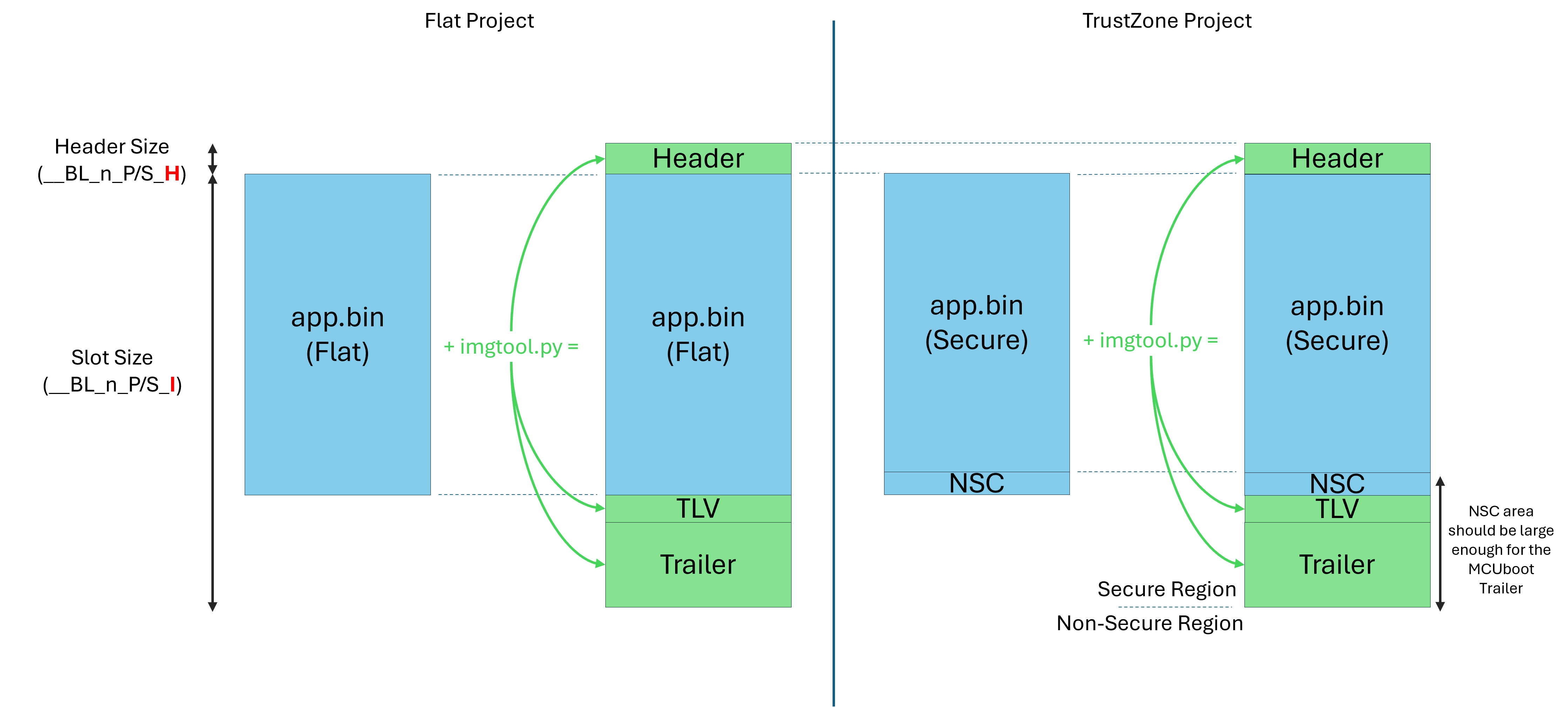
MCUboot Layout
imgtool.py siging script adds header and trailer to user binary
Getting Started: Signing Tool Prerequisite
To use the MCUboot signing tool, ensure you have Python 3.x installed on your system. Then install the Python packages required for the signing tool with the following command (modifying the path as needed depending on current directory):
Getting Started: Converting an Application Project to an MCUboot Image
MCUboot application images must execute from the image slot defined by the MCUboot project. They are also limited to a single downloadable flash region. All of this is configured in the MCUboot module and the information is added to the generated SecureBundle (.sbd) file in the MCUboot project.
Any existing project can be converted to an MCUboot image.
If the project was created with a version prior to FSP v3.0.0, update the linker script to the v3.0.0 version before using it as an MCUboot application image.
Right click the project to convert in e² studio or RASC and select Properties.
Open C/C++ Build and select Build Variables.
Click Add...
For Variable Name, enter SmartBundle. For Type, select File. Browse to the *.sbd file created alongside the *.elf file for the associated MCUboot project. If the MCUboot project was specified as the Preceding Project during project creation, this step is done automatically.
Click OK, then Apply and Close.
To convert a TrustZone image, follow the steps above for the Secure project. The Non-Secure project will already use the SmartBundle from the Secure project which will inherit required data from the MCUboot SmartBundle.
MCUboot application images must also be signed to work with MCUboot. At a minimum, this involves adding a SHA and MCUboot specific constant data called boot magic in the image trailer. The size of the image trailer is (5 * BOOT_MAX_ALIGN) + (BOOT_MAX_IMG_SECTORS * min-write-size * 3).
Signing can be done on the as a post-build step in e² studio. To sign the image as a post-build step:
If Linux is used to develop the application image, change the MCUboot property Signing > Python to python3.
Build the bootloader project to generate the *.bld file. Make sure to build the bootloader project on the same computer as the application image to ensure the path to the signing script is correct.
Define environment variables in the Properties of the application image project in e² studio.
Right click the application image project, and select Properties.
Select C/C++ Build > Environment on the left.
Click Add...
Define the following environment variables one at a time:
MCUBOOT_IMAGE_VERSION: Set to the version of the application image.
MCUBOOT_IMAGE_SIGNING_KEY: Set the path to the key used for signing. If signing is not required, do not set this variable. If example keys are used, set MCUBOOT_IMAGE_SIGNING_KEY as follows (replace <boot_project> with the bootloader project path):
MCUBOOT_IMAGE_ENC_KEY: Set the path to the key used for encryption. If encryption is not required, do not set this variable. If example keys are used, set MCUBOOT_IMAGE_ENC_KEY as follows (replace <boot_project> with the bootloader project path):
MCUBOOT_APP_BIN_CONVERTER: Optional. Set to path to objcopy, arm-none-eabi-objcopy, fromelf, or ielftool. Not required if one of these tools is on the path.
Build the project.
The signed image is output next to the application <project>.elf file with the name <project>bin.signed.
FSP 6.0.0 and newer
An FSP Solution project must be created in order to set up the bootloader slots; the slot size and header information was previously in the MCUboot module. Below is a description of the region naming rules and how to manually create the Solution for a single and multi-image use case. There are also templates that can be used as a starting point instead.
Bootloader region encoding in FSP 6.0.0
The header and image regions have to be named in the manner described below in the Solution project:
FLASH_<core>_(B|S| ) - Indicates bootloader area or primary area. These are created by default and cannot be renamed.
Examples:
FLASH_CM85_B: CM85 Bootloader area.
FLASH_CM85_S: CM85 Primary area.
FLASH_CM23 : CM23 Primary area.
__BL: Indicates this is a bootloader symbol.
_: delimiter between fields.
([0-9])|S: Image definitions field.
S indicates the Scratch area.
0-9 correspond to traditional image IDs (only using 0/1 in legacy).
_: delimiter between fields.
(P|S): Indicates Primary or Secondary area.
S Secondary areas must have both Header (H) and Image (I) component.
P Primary areas must not have an I component (as the Image component is defined by the solution application region).
Secondary header must be the same size as Primary header.
Secondary images must be the same size as the area allocated for the project (Primary Image).
Headers must immediately precede the Image/application space.
_: delimiter between fields
(H|I): Indicates bootloader Header or Image component (not used with Scratch).
H indicates the MCUboot Header for Primary or Secondary (P/S) areas (use 0x200 for compatibility).
I indicates the MCUboot Secondary (S) Image allocation space (not used with Primary images).
Bootloader flash area size must be an integer multiple of the largest erase size on the mcu.
Primary or Secondary area size (including header and trailer) must be an integer multiple of the largest erase size on the mcu.
Examples:
__BL_0_P_H: Image 0 Primary Header.
__BL_0_S_H: Image 0 Secondary Header.
__BL_1_S_I: Image 1 Secondary Image.
__BL_S : Scratch area.
Using Bootloader Solution Templates
MCUBoot templates can be used to generate a pre-configured Solution and required projects. The templates are available in the New C/C++ Project wizard in MCUBoot.
Below is a list of the currently supported templates in FSP.
Device
Crypto engine
MCUboot mode
Crypto stack
Flat
TrustZone
RA0 series — Cortex-M23
RA0L1
-
Overwrite
OCrypto
✅
❌
RA2 series — Cortex-M23
RA2A2
AES_b
XIP via MMF
mbedTLS
✅
❌
RA2E1 / RA2E2 / RA2L1
AES
Overwrite
mbedTLS
✅
❌
Overwrite
OCrypto
✅
❌
RA6 series — Cortex-M4
RA6M1 / RA6M2 / RA6M3 / RA6T1
SCE7
XIP via MMF
mbedTLS
✅
❌
RA4 series — Cortex-M33
RA4E2 / RA4T1
TRNG Only
Overwrite
mbedTLS
✅
❌
RA4E1 / RA4M2 / RA4M3
SCE9 / SCE9_TRNG
Overwrite
mbedTLS
✅
❌
RA6 series — Cortex-M33
RA6E2 / RA6T3
TRNG Only
Overwrite
mbedTLS
✅
❌
RA6E1 / RA6M4 / RA6M5
SCE9 / SCE9_TRNG
Overwrite
mbedTLS
✅
❌
RA8 series — Cortex-M85
RA8E1 / RA8E2
RSIP-E51A_TRNG
Overwrite
mbedTLS
✅
❌
RA8D1 / RA8M1 / RA8T1
RSIP-E51A
Overwrite
mbedTLS
✅
❌
RA8 series — dual core (M85 + M33)
RA8D2 / RA8M2 / RA8P1 / RA8T2
RSIP-E50D
Overwrite
mbedTLS
✅
❌
Single-Image Bootloader Setup
Create the bootloader and set up any required configurations.
Build the bootloader project.
Create the application project, selecting the bootloader project as the "Preceding project" in the e2 studio wizard. The SmartBundle (.sbd) will be automatically linked.
Build the application project.
Create an "FSP Solution Project (Advanced)" and chose the final project in the chain (typically the application project).
Create the Header and Image regions according to the encoding described above.
Build the Solution project.
Multi-Image Bootloader Setup
Create the bootloader and set up any required configurations.
Build the bootloader project.
Repeat the following steps for each application image (Image 0, Image 1, ..., Image n):
Create an application project, selecting the bootloader project as the "Preceding project" in the e2 studio wizard. The SmartBundle (.sbd) will be automatically linked.
Build the application project.
Create an "FSP Solution Project (Advanced)" and select the final project in the chain (typically the first application project). <raSmartBundles\><bundle\>${workspace_loc:/bootloader_project}/Debug/bootloader_project.sbd\</bundle\><bundle\>${workspace_loc:/app_image0}/Debug/app_image0.sbd\</bundle\></raSmartBundles\>
Create the Header and Image regions according to the encoding described in the previous section. Example for Image 0, 1, 2, 3: __BL_0_P_H 0x10000 0x200 __BL_0_P_I 0x10200 0xFE00 __BL_0_S_H 0x20000 0x200 __BL_0_S_I 0x20200 0xFE00 __BL_1_P_H 0x30000 0x200 __BL_1_P_I 0x30200 0xFE00 __BL_1_S_H 0x40000 0x200 __BL_1_S_I 0x40200 0xFE00 __BL_2_P_H 0x50000 0x200 __BL_2_P_I 0x50200 0xFE00 __BL_2_S_H 0x60000 0x200 __BL_2_S_I 0x60200 0xFE00 __BL_3_P_H 0x70000 0x200 __BL_3_P_I 0x70200 0xFE00 __BL_3_S_H 0x80000 0x200 __BL_3_S_I 0x80200 0xFE00
Manually edit solution.xml to add the required primary image paths (Image 1, 2, 3). Then refresh the solution project. <raSmartBundles\><bundle\>${workspace_loc:/bootloader_project}/Debug/bootloader_project.sbd\</bundle\><bundle\>${workspace_loc:/app_image0}/Debug/app_image0.sbd\</bundle\><bundle\>${workspace_loc:/app_image1}/Debug/app_image1.sbd\</bundle\><bundle\>${workspace_loc:/app_image2}/Debug/app_image2.sbd\</bundle\><bundle\>${workspace_loc:/app_image3}/Debug/app_image3.sbd\</bundle\></raSmartBundles\>
Build the Solution project.
Repeat the following steps for each application image (Image 0, Image 1, ..., Image n):
Create an alternate memory regions file with FLASH_START and FLASH_LENGTH values to match the corresponding __BL_<n>_P_I partition.
Create the alternate memory regions file (For example: memory_regions_ext.lld for LLVM) in the application project directory by making a copy of the generated memory regions file in the Debug folder.
In that file, set FLASH_START to the start address of __BL_<n>_P_I and FLASH_LENGTH to the partition size. For example: FLASH_START = 0x10200; FLASH_LENGTH = 0xFE00;
Save the file.
Add the alternate memory regions files to the linker script.
Edit the fsp.lld file to include the new memory regions file instead of the default.
Build the project.
Getting Started: Download and Debug
For projects that do not use TrustZone, debug the MCUboot project using the default configuration. Before running, load the signed image to the address specified in the signing comment in ra_cfg/mcu-tools/include/mcuboot_config/mcuboot_config.h. This can be done with the Load Ancillary File button when debugging in e² studio. Upgrade images can be loaded to the upgrade image slots using the same method.
Note
e² studio projects targeting RA8 devices that do not use TrustZone must disable the "Set TrustZone secure/non-secure boundaries" setting (Debug Configurations > Debugger > Connection Settings > TrustZone > Set TrustZone secure/non-secure boundaries).
For TrustZone projects, debug using the Secure project to ensure the IDAU is partitioned correctly when debugging in e² studio. Make the following modifications before debugging in e² studio:
In the Debug Configurations for your project, on the Startup tab, click Add... to add the MCUboot project *.elf file (Image and Symbols), and optionally the Non-Secure project *.elf file.
For the Secure and Non-Secure project *.elf file, load Symbols Only.
After starting to debug, load the signed Secure image and the signed Non-Secure image into the addresses specified in the signing comment in ra_cfg/mcu-tools/include/mcuboot_config/mcuboot_config.h. This can be done with the Load Ancillary File button when debugging in e² studio. Upgrade images can be loaded to the upgrade image slots using the same method.
Confirming Upgrade in Swap Mode
In Swap Mode operation, if the upgrade image is signed with the –pad option, MCUboot will install that image as a temporary update where if nothing else is done, a reboot will cause MCUboot to revert to the image version that was swapped out during the upgrade. In order for the updated image to prevent this reversion and make the update permanent, the boot_set_confirmed() must be called from the application.
To avail this capability in the application image, from the Stacks tab, add New > Bootloader > MCUboot Image Utilities (Swap Mode). Resolve any constraint errors and edit configurations as desired.
In src/hal_entry.c, drag in Developer Assistance > HAL/Common > MCUboot Image Utilities > Quick Setup > Confirm Primary Image. Add a call to boot_set_confirmed() in the application and confirm the image in the primary slot.
XIP Mode operation
XIP mode is enabled selecting "Direct XIP" as the Upgrade Mode option in the configurator or by defining "MCUBOOT_DIRECT_XIP" in the mcuboot config file. The linker script defines the symbol "XIP_SECONDARY_SLOT_IMAGE" by default to 0. To link an application to the secondar slot in XIP mode, set XIP_SECONDARY_SLOT_IMAGE to 1 in the application linker script. Direct XIP mode does not support TrustZone projects.
XIP Mode with Memory Mirror Function (MMF)
Note
Memory Mirror Functions is available on some MCUs, please check the hardware user manual for the availability.
This mode only available in linear memory mode.
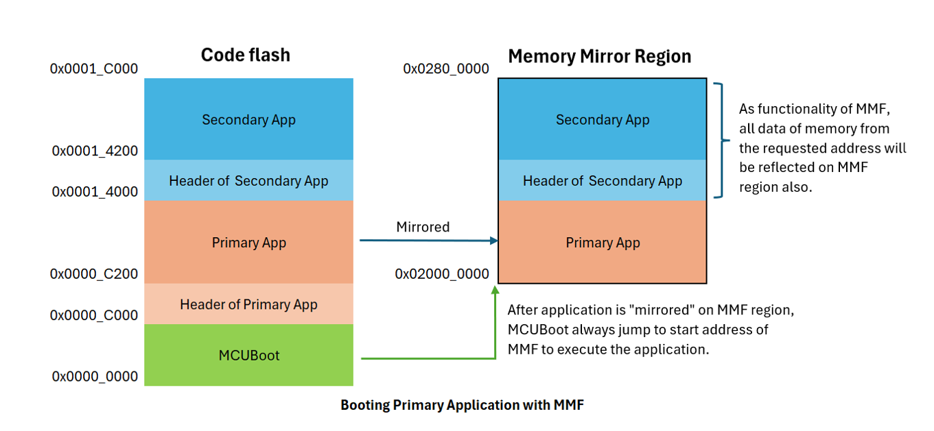
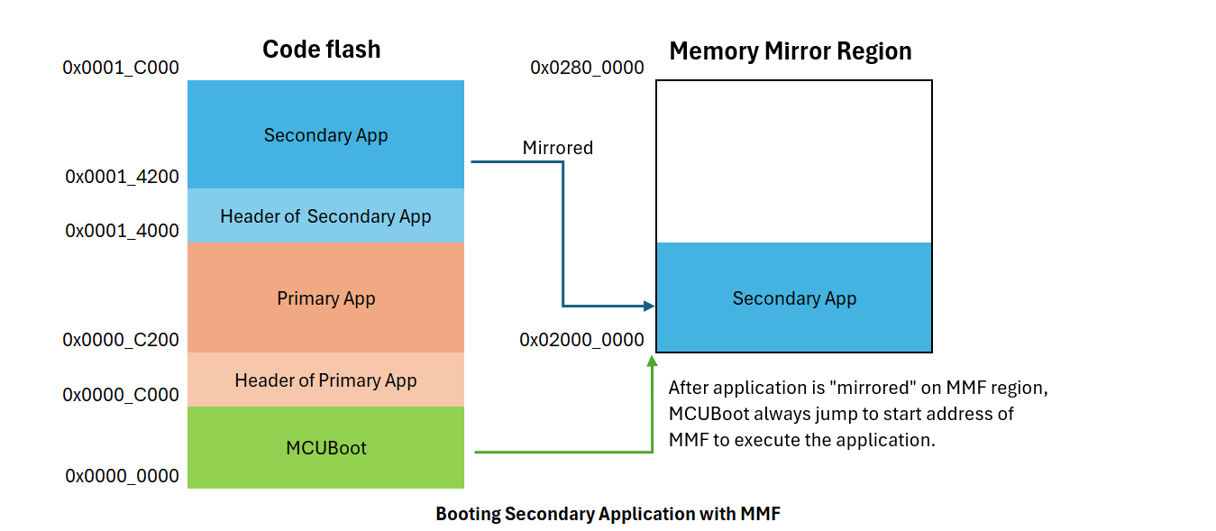
When "Memory Mirror Function (MMF) support" under Common > Flash Layout is enabled, MCUBoot decides which image will be "mirrored". After the image is reflected on MMF region, the MCUBoot will start booting the application from start address of MMF.
Booting Primary Application with MMF
Booting Secondary Application with MMF
Dual Bank operation
MCUboot can be used with Dual bank mode (with Flash HP or Flash LP) to leverage the advantages of dual bank flash operation. When Dual Bank mode is enabled, only the XIP upgrade mode can be used.
Note
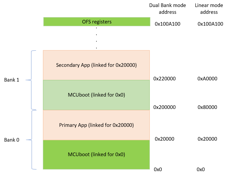
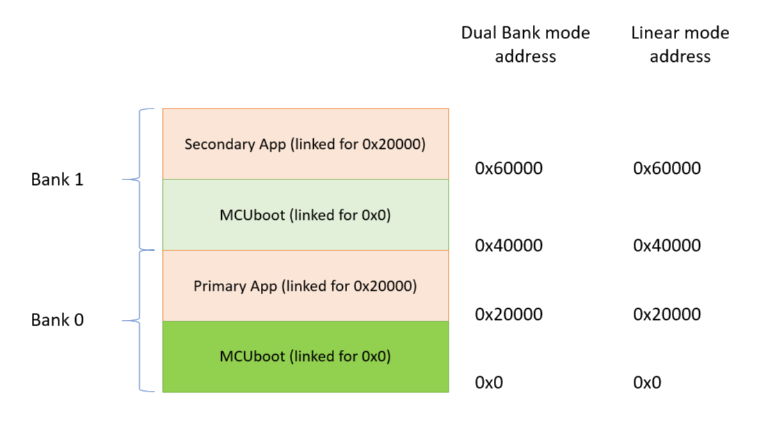
Unlike in normal XIP Mode operation, the linker script symbol "XIP_SECONDARY_SLOT_IMAGE" must be undefined in Dual Bank mode. An example flash layout in this configuration for a 1 MB is shown below. Note that there are 2 copies of the bootloader, one in Bank 0 and another in Bank 1.
MCUboot Dual Bank layout of Flash HP for 1 MB Memory
For this example layout, the following files are generated when Dual Bank mode with XIP is enabled:
Bootloader Project: srec file linked to address 0 and includes the OFS region.
Application Project (Primary): signed bin file linked to address 0x20000.
Application Project (Secondary): signed bin file linked to address 0x20000.
With Flash HP in Dual Bank mode, the available flash memory is split into two halves and referred to as Bank 0 and 1. In this example Bank 0 would span from address 0x0 - 0x7FFFF and Bank 1 from 0x200000 - 0x27FFFF. In Linear mode, it is possible to program the Bank 1 area by programming to 0x80000 - 0xFFFFF.
MCUboot Dual Bank layout of Flash LP for 512 KB Memory
With Flash LP in Dual Bank mode, the available flash memory is also split into two bank areas and referred to as Bank 0 and 1. In this example Bank 0 would span from address 0x0 - 0x3FFFF and Bank 1 from 0x40000 - 0x7FFFF. In Linear mode, it is possible to program the Bank 1 area by programming to 0x40000 - 0x7FFFF.
Programming in Dual Bank Mode with Flash HP
The bootloader must be duplicated in Dual Bank mode. Bank 0 can be programmed using the srec file generated from the MCUboot project; this will also program the OFS region which contains the dual bank enable bit, so it must either be programmed last if each file is programmed independently. Another option is to combine all images: MCUboot in Bank 0, primary image, MCUboot in Bank 1 (no OFS), and secondary image (optional). To program MCUboot to Bank 1, offset MCUboot by half the flash size and cut off the OFS region (0x0100A100 to address 0x0100A2FF on CM33 MCUs that support dual bank). Using srec-cat for a 1 MB flash MCU (0x80000 flash per bank), an example command to create the bootloader image for Bank 1: "srec_cat MCUboot_dualbank.srec -crop 0 0x80000 -offset 0x80000 -o MCUboot_dualbank_offset.srec". The application project for Bank 1 can be similarly offset using srec_cat: "srec_cat app1.bin.signed -binary -offset 0xA0000 -o app1_offset.srec", where 0xA0000 is 0x80000 (half the flash) + 0x20000 (MCUboot size). The signed binary file for Bank 0 can be converted to srec format using srec_cat: "srec_cat app0.bin.signed -binary -offset 0x20000 -o app0.srec"
To combine all the files into one srec file, use "srec_cat MCUboot_dualbank.srec MCUboot_dualbank_offset.srec app0.srec app1_offset.srec -o combined_srec".
Programming in Dual Bank Mode with Flash LP
To use Dual Bank Mode with Flash LP, enable Dual Bank Mode (Flash LP) in the MCUboot stack under Property > Common > General.
Similar to Dual Bank Mode with Flash HP, the bootloader must also be duplicated in Dual Bank mode. But the MCUBoot project does not need to be programmed last, because Flash LP does not use the OFS region to enable/disable the dual bank mode.
Dual bank booting without reset
Note
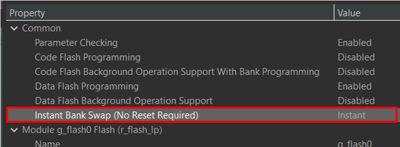
This feature only available on MCUs which support flash_lp and Instant Bank Swap.
Instant Bank Swap option under Flash stack
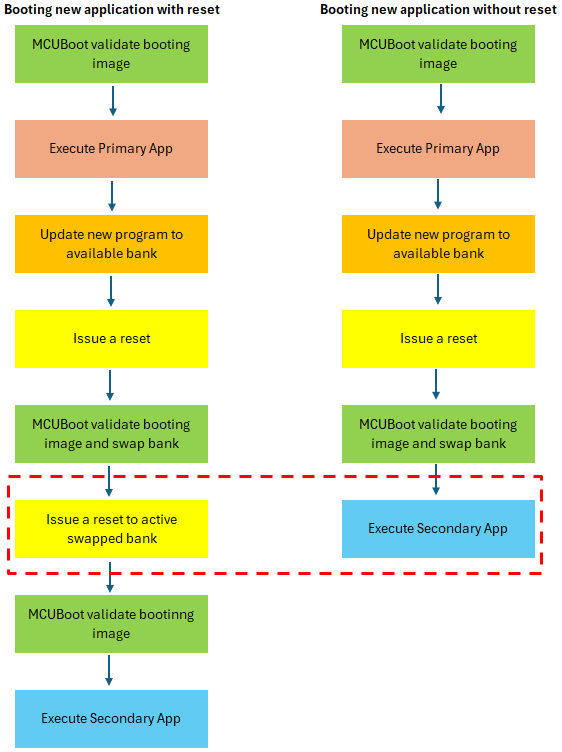
The picture below shows the execution sequence with Reset and Without Reset (Instant Bank Swap).
Software flow differences between booting with and without reset
External Memory Support
QSPI
QSPI support for secondary image storage can be enabled in the configurator. The bootloader expects the QSPI memory to be pre-configured by user code in the bootloader for read/write operation. The bootloader code operates under the assumption that the user has configured the QSPI in Extended-SPI mode and that R_QSPI_Open() has been called prior to invoking boot_go();. For example, on the EK_RA6M4 which has the MX25L25645G QSPI flash, after adding the QSPI module to the project, calling the following snippet will configure the QSPI for read/write operation:
For a more detailed example on how to initialize the QSPI device, refer to the QSPI module. The QSPI sector size must be the same as that of the MCU internal flash (BSP_FEATURE_FLASH_HP_CF_REGION1_BLOCK_SIZE) for swap mode operation.
OSPI_B
OSPI_B support for secondary image storage can be enabled in the configurator for RA8: The bootloader expects the OSPI memory to be pre-configured by user code in the bootloader for read/write operation. The bootloader code operates under the assumption that the user has initialized the OSPI_B by calling R_OSPI_B_Open() prior to invoking boot_go();.
The OSPI sector size must be the same as that of the MCU internal flash (BSP_FEATURE_FLASH_HP_CF_REGION1_BLOCK_SIZE) for swap mode operation.
Note
: The user can specify the OSPI erase block size for the area that will be erased/written to by MCUBoot. Do not use OSPI regions that span multiple block erase sizes or block erase sizes larger than the code flash erase size of 32K.
MCUboot Memory Map
For single image projects with no external memory support, the default memory map looks like:
MCUboot Memory Map
For projects with 2 separately updateable images (used for TrustZone applications where the Secure and Non-Secure images can be updated separately), the default memory map with no external memory support looks like:
MCUboot Memory Map (TrustZone)
For single image projects with QSPI, the default memory map looks like:
MCUboot Memory Map with QSPI
MCUboot verification options
MCUboot in FSP supports the following secure image verification options
Hash verification only (SHA256).
Hash and signature verification (ECDSA-P256, ECDSA-P384, RSA-2048, RSA-3072, ML-DSA-44, ML-DSA-65, and ML-DSA-87).
Hash, signature verification and image encryption (ECIES-P256 and RSA-OAEP-2048 with AES-128).
Hash and image encryption only.
MCUboot also supports signature verification using EdDSA-25519 and image encryption using AES-KW-128 and AES-KW-256 but those are currently not supported in FSP.
Limitations
MCUboot swap mode is not functional with OSPI_B external storage.
Notes
When encryption is enabled, MCUboot requires the image in the primary slot to be unencrypted. Only the image loaded in the secondary slot can be encrypted.
MCUboot Crypto Stack Options
The following crypto stacks can be used with MCUboot in FSP:
MbedTLS, which is hardware accelerated on all RA devices. On the RA2 which has an AES engine only, ECC/RSA/SHA operations are in software.
Post Quantum Crypto (PQC) can optionally be used for ML-DSA operations
Ocrypto (TRNG Only) can be used with some devices. See Licensed Devices.
TinyCrypt (S/W Only) can be used with all devices.
TinyCrypt (H/W Accelerated) has AES operations accelerated for the RA2 family only. When using MCUboot without encryption there is no difference between using this or the S/W only version.
SCE9 Protected Mode on devices that have the SCE9 (eg: RA6M4, RA4M3, RA4M2)
MbedTLS provides the best performance for MCUBoot signature verification on the RA6 and RA4 devices but has a much larger code footprint compared to TinyCrypt. For RA2 devices TinyCrypt is the best option.
MCUboot boot time
The time from Reset to executing the application will depend on how quickly MCUboot finishes execution. This is dependent on a variety of factors including
The crypto algorithms chosen for image verification and whether hardware acceleration is enabled. Hardware accelerated SHA256 will be the fastest while encryption enabled modes will be the slowest.
The operating clock speeds.
Whether flash programming was required.
Using SCE9 Protected Mode Crypto Stack
Using this crypto stack with MCUBoot provides additional security by ensuring that any keys that are used were securely provisioned for the specific device. The Application Note "Installing and Updating Secure Keys for RA Family" (R11AN0496) provides detailed steps on how to go about installing these keys. Since the section "Preparing Keys for Installation and Update Using RFP" document currently only provides information on how to install an AES key, this section will provide information on how to install an ECC public key. These steps can be used to install the public keys used for image verification or the keys used for image encryption.
Note
When using the SCE9 Protected Mode Stack with MCUboot it is required that the public keys in the format described in the "MCUboot Example Keys" module in the stack is also provided in the project.
Installing public keys used for signature verification
Generate an ECC key pair. There are various ways to do this but you can use openSSL to do so: "openssl ecparam -name secp256k1 -genkey -noout -out my_ecc_secp256k1_key.pem".
Once the key is generated, in order to install the public key using RFP (Renesas Flash Programmer) the user needs to have their own UFPK (User Factory Programming Key) and W-UFPK (Wrapped User Factory Programming Key). Refer to R11AN0496 on how to obtain these keys.
Once the UFPK and W-UFPK are available, we need to extract the public key from the pem file. The public key can be viewed by using "openssl ec -noout -text -in my_ecc_secp256k1_key.pem". Note that when the ECC public key is printed out this way, it will contain a 0x04 ASN.1 prefix at the start, which should be discarded.
Use the rfp-util.exe utility from the RFP installation folder to wrap the public key using the UFPK and W-UFPK into a format that can be installed by RFP and the factory bootloader on the MCU.
Use RFP as described in R11AN0496 to install the key to the location of mcuboot_sce9_key section.
These are examples that install the default keys provided with MCUboot in ra/mcu-tools/MCUboot/. The examples assume that UFPK and W-UFPK are already available.
//Print out the EC-P256 Public Key using openSSL
C:\ openssl ec -noout -text -in root-ec-p256.pem
read EC key
Private-Key: (256 bit)
priv:
d7:98:d5:2f:83:01:24:3b:d3:54:2b:7e:55:ed:4c:
74:61:19:00:b0:f9:50:5a:82:4f:e1:e8:ec:06:3b:
cf:f1
pub:
04:2a:cb:40:3c:e8:fe:ed:5b:a4:49:95:a1:a9:1d:
ae:e8:db:be:19:37:cd:14:fb:2f:24:57:37:e5:95:
39:88:d9:94:b9:d6:5a:eb:d7:cd:d5:30:8a:d6:fe:
48:b2:4a:6a:81:0e:e5:f0:7d:8b:68:34:cc:3a:6a:
fc:53:8e:fa:c1
ASN1 OID: prime256v1
NIST CURVE: P-256
//Use the public key (ignore the 0x04 ASN.1 prefix) in the RFP command line to convert the public key into an installable format
// From the bootloader map file determine the address of mcuboot_sce9_key section
Use RFP to install "ECC_pub_install.rkey" as described in "Installing and Updating Secure Keys for RA Family" (R11AN0496) to the address where the mcuboot_sce9_key section is located.
//Use the public key in the RFP command line to convert the public key into an installable format. Note that for RSA, the public modulus has to be concatenated to the public exponent (typically 65537 in 32 bits 00010001 as shown in the asn1parse output above) and then padded with 4 words of 0.
// From the bootloader map file determine the address of mcuboot_sce9_key section
Use RFP to install "RSA_pub_install.rkey" as described in "Installing and Updating Secure Keys for RA Family" (R11AN0496) to the address where the mcuboot_sce9_key section is located.
//Use the public key in the RFP command line to convert the public key into an installable format. Note that for RSA, the public modulus has to be concatenated to the public exponent (typically 65537 in 32 bits 00010001 as shown in the asn1parse output above) and then padded with 4 words of 0.
// From the bootloader map file determine the address of mcuboot_sce9_key section
Use RFP to install "RSA_3072_pub_install.rkey" as described in "Installing and Updating Secure Keys for RA Family" (R11AN0496) to the address where the mcuboot_sce9_key section is located.
Examples
Basic Example
This is an example of using MCUboot in an application.