 |
RX Flexible Software Package Documentation
Release v1.0.0
|
|
|
RX Flexible Software Package Documentation
Release v1.0.0
|
|
The wealth of resources available to learn about and use e2 studio and FSP can be overwhelming on first inspection, so this section provides a Starting Development Guide with a list of the most important initial steps. Following these highly recommended first 11 steps will bring you up to speed on the development environment in record time. Even experienced developers can benefit from the use of this guide, to learn the terminology that might be unfamiliar or different from previous environments.
Renesas e2 studio is a development tool encompassing code development, build, and debug. e2 studio is based on the open-source Eclipse IDE and the associated C/C++ Development Tooling (CDT).
When developing for RX MCUs, e2 studio hosts the Renesas Flexible Software Package (FSP). FSP provides a wide range of time saving tools to simplify the selection, configuration, and management of modules and threads, to easily implement complex applications. The time saving tools available in e2 studio and FSP include the following:

e2 studio organizes project work based on Perspectives, Views, Windows, Panes, and Pages (sometimes called Tabs). A window is a section of the e2 studio GUI that presents information on a key topic. Windows often use tabs to select sub-topics. For example, an editor window might have a tab available for each open file, so it is easy to switch back and forth between them. A window Pane is a section of a window. Within a window, multiple Panes can be opened and viewed simultaneously, as opposed to a tabbed window, where only individual content is displayed. A memory-display Window, for example, might have multiple Panes that allow the data to be displayed in different formats, simultaneously. A Perspective is a collection of Views and Windows typical for a specific stage of development. The default perspectives are a C/C++ Perspective, an FSP Configuration Perspective and a Debug Perspective. These provide specific Views, Windows, Tabs, and Panes tailored for the common tasks needed during the specific development stage.
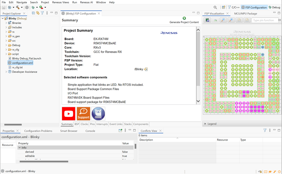
In addition to managing project development, selecting modules, configuring them and simplifying code development, e2 studio also hosts the engine for automatically generating code based on module selections and configurations. The engine continually checks for dependencies and automatically adds any needed lower level modules to the module stack. It also identifies any lower level modules that require configuration (for example, an interrupt that needs to have a priority assigned). It also provides a guide for selecting between multiple choices or options to make it easy to complete a fully functional module stack.
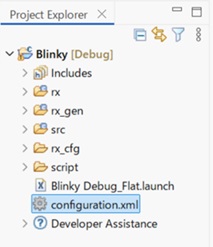
The Generate Project Content function takes the selected and configured modules and automatically generates the complete and correct configuration code. The code is added to the folders visible in the Project Explorer window in e2 studio. The configuration.xml file in the project folder holds all the generated configuration settings. This file can be opened in the GUI-based FSP Configuration editor to make further edits and changes. Once a project has been generated, you can go back and reconfigure any of the modules and settings if required using this editor.
To develop applications with FSP, start with one of the Renesas RX MCU Evaluation Kits. The Renesas RX MCU Evaluation Kits are designed to seamlessly integrate with the e2 studio.
Ordering information, Quick Start Guides, User Manuals, and other related documents for all RX MCU Evaluation Kits are available at https://www.renesas.com/rx.
The following are the minimum PC requirements to use e2 studio:
Detailed installation instructions for the e2 studio and the FSP are available on the Renesas website https://www.renesas.com/fsp. Review the release notes for e2 studio to ensure that the e2 studio version supports the selected FSP version. The starting version of the installer includes all features of the RX MCUs.
e2 studio can work with several toolchains and toolchain versions
such as the GCC for Renesas RX compiler and Renesas CCRX. A version of the Renesas compiler is included in the e2 studio installer and has been verified to run with the FSP version.
FSP licensing includes full source code, limited to Renesas hardware only.
In e2 studio, all FSP applications are organized in RX MCU projects. Setting up an RX MCU project involves:
These steps are described in detail in the next two sections. When you have existing projects already, after you launch e2 studio and select a workspace, all projects previously saved in the selected workspace are loaded and displayed in the Project Explorer window. Each project has an associated configuration file named configuration.xml, which is located in the project's root directory.
Double-click on the configuration.xml file to open the RX MCU Project Editor. To edit the project configuration, make sure that the FSP Configuration perspective is selected in the upper right hand corner of the e2 studio window. Once selected, you can use the editor to view or modify the configuration settings associated with this project.

configuration.xml file) is saved, a verbose RX Project Report file (rx_cfg.txt) with all the project settings is generated. The format allows differences to be easily viewed using a text comparison tool. The generated file is located in the project root directory.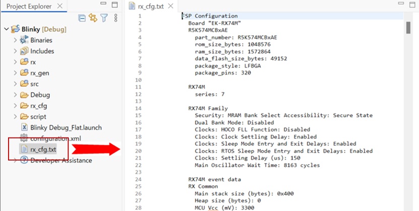
The RX Project Editor has a number of tabs. The configuration steps and options for individual tabs are discussed in the following sections.
During project creation, you specify the type of project, give it a project name and location, and configure the project settings for version, target board, whether an RTOS is included, the toolchain version, and the beginning template. This section includes easy-to-follow step-by-step instructions for all of the project creation tasks. Once you have created the project, you can move to configuring the project hardware (clocks, pins, interrupts) and the parameters of all the modules that are part of your application.
For RX MCU applications, generate a new project using the following steps:
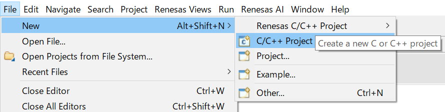
Click on File > New > RX C/C++ Project.

Then click on the type of template for the type of project you are creating.
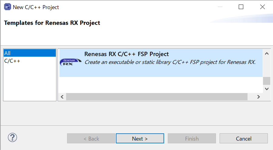
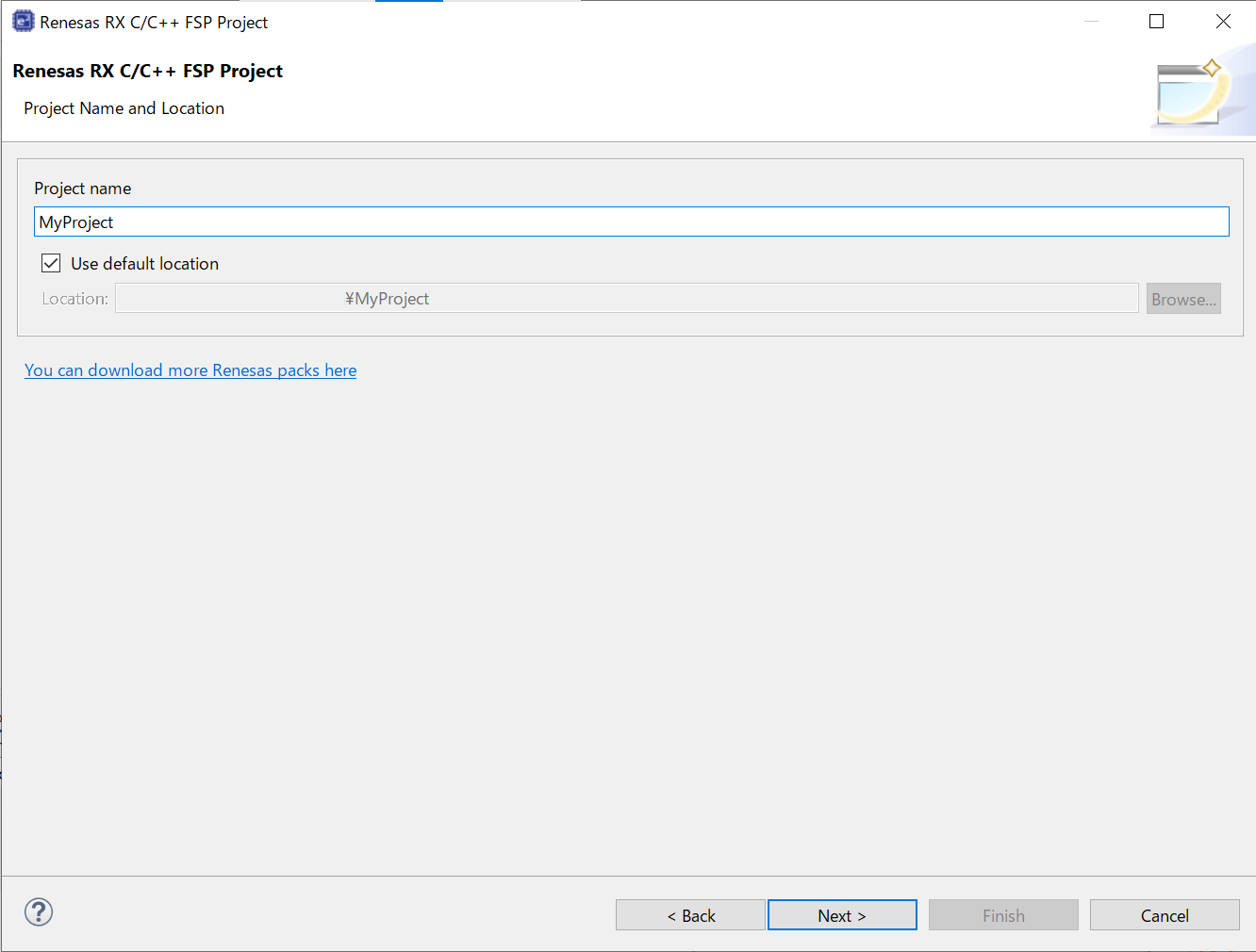
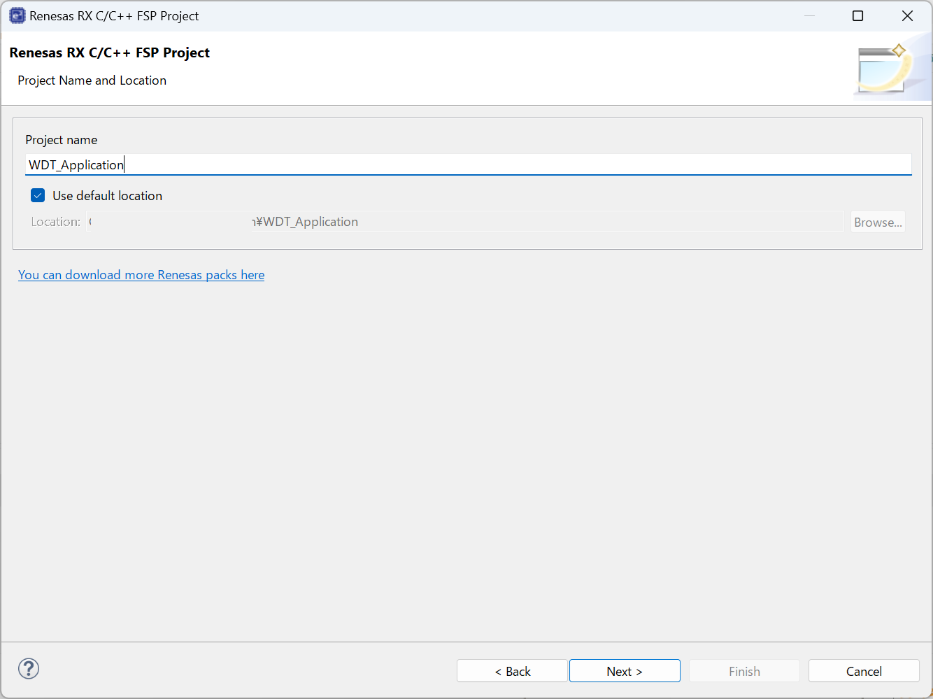
Select a project name and location.
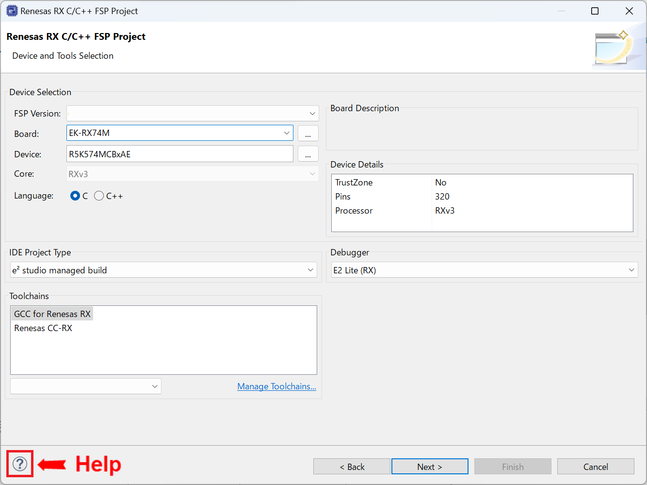
In the Project Configuration window select the hardware and software environment:
Click Next.
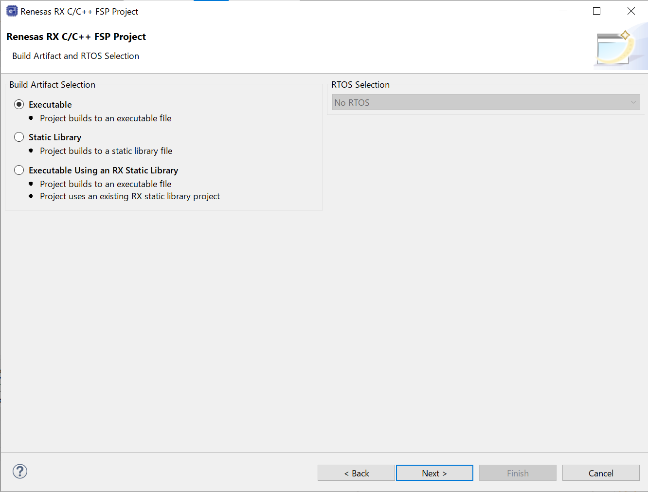
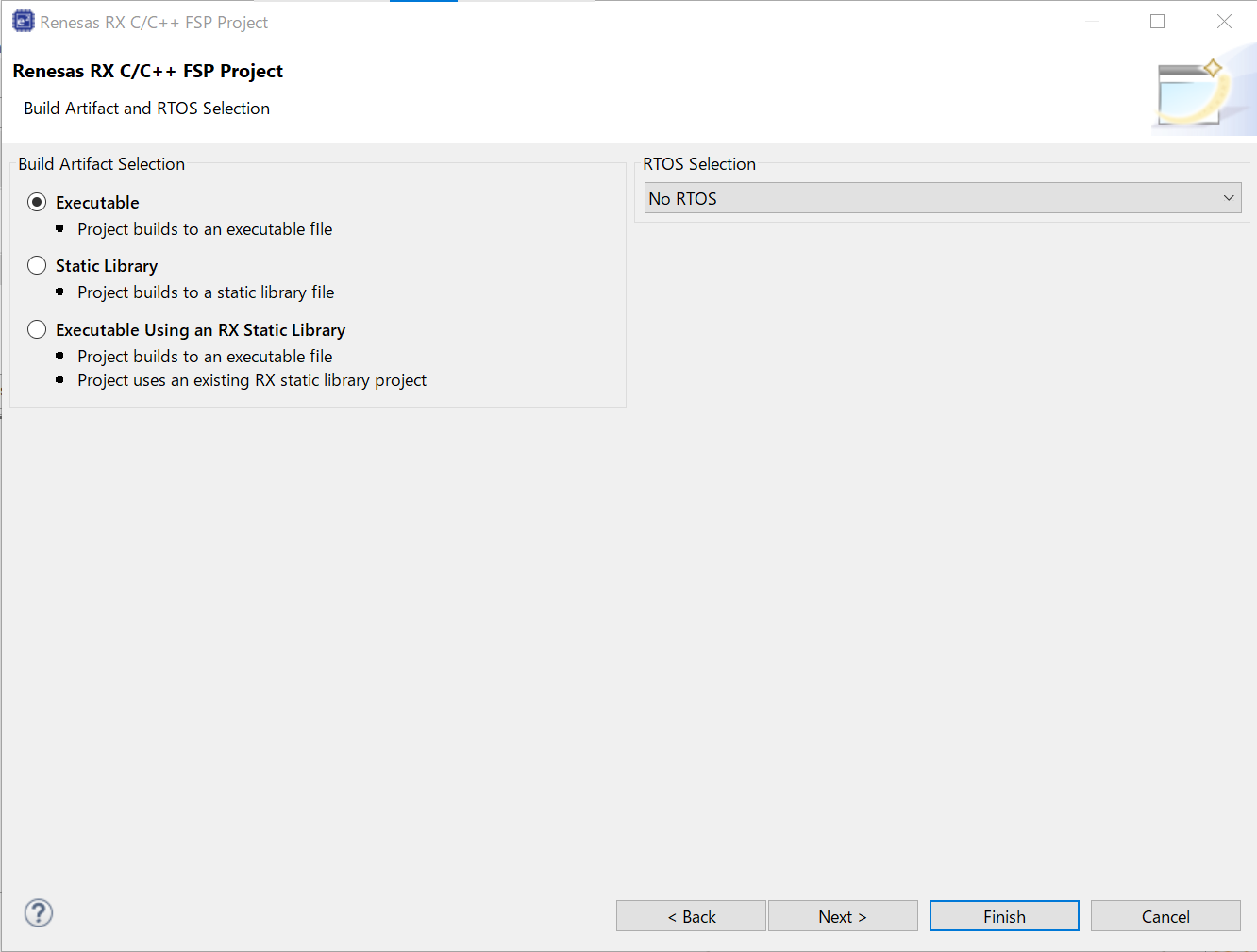
In the next window, select the build artifact and RTOS.
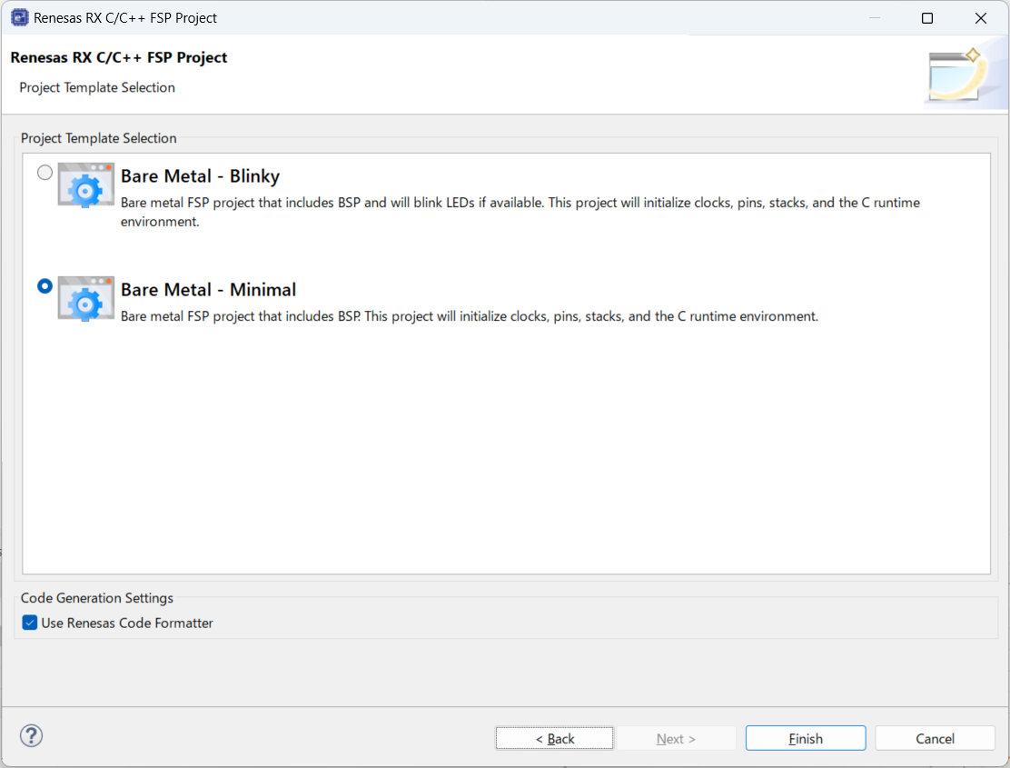
In the next window, select a project template from the list of available templates. By default, this screen shows the templates that are included in your current RX MCU pack. Once you have selected the appropriate template, click Finish.
When the project is created, e2 studio displays a summary of the current project configuration in the RX MCU Project Editor.
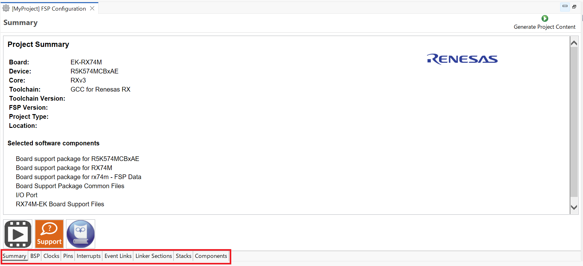
On the bottom of the RX MCU Project Editor view, you can find the tabs for configuring multiple aspects of your project:
The functions and use of each of these tabs is explained in detail in the next section.
Each of the configurable elements in an FSP project can be edited using the appropriate tab in the FSP Configuration editor window. Importantly, the initial configuration of the MCU after reset and before any user code is executed is set by the configuration settings in the BSP, Clocks and Pins tabs. When you select a project template during project creation, e2 studio configures default values that are appropriate for the associated board. You can change those default values as needed. The following sections detail the process of configuring each of the project elements for each of the associated tabs.
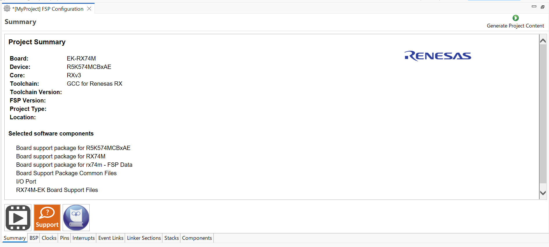
The Summary tab, seen in the above figure, identifies all the key elements and components of a project. It shows the target board, the device, toolchain and FSP version. Additionally, it provides a list of all the selected software components and modules used by the project. This is a more convenient summary view when compared to the Components tab.
The summary tab also includes handy icons with links to the Renesas YouTube channel, the Renesas support page and to the RX FSP User Manual that was downloaded during the installation process.
The BSP tab shows the currently selected board (if any) and device. The Properties view is located in the lower left of the Project Configurations view as shown below.
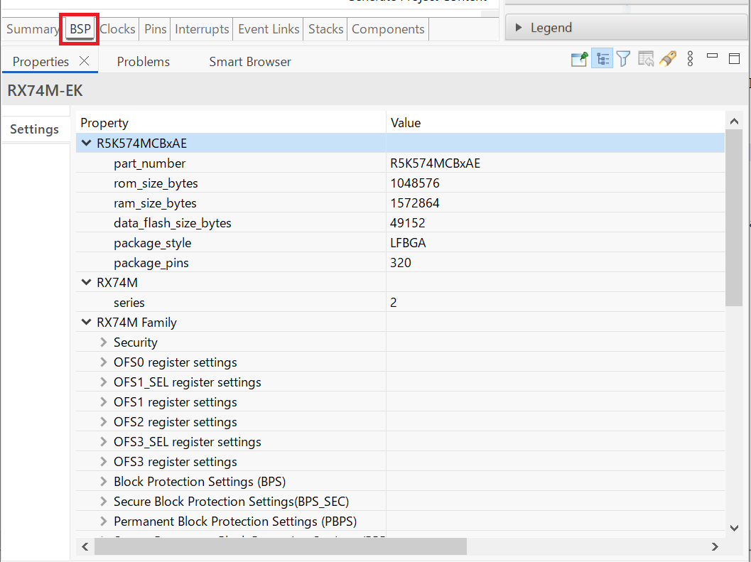
The Properties view shows the configurable options available for the BSP. These can be changed as required. The BSP is the FSP layer above the MCU hardware. e2 studio checks the entry fields to flag invalid entries. For example, only valid numeric values can be entered for the stack size.
When you click the Generate Project Content button, the BSP configuration contents are written to rx_cfg/fsp_cfg/bsp/bsp_cfg.h
This file is created if it does not already exist.
The Clocks tab presents a graphical view of the MCU's clock tree, allowing the various clock dividers and sources to be modified. If a clock setting is invalid, the offending clock value is highlighted in red. It is still possible to generate code with this setting, but correct operation cannot be guaranteed. In the figure below, the USB clock USBCLK has been changed so the resulting clock frequency is 60 MHz instead of the required 48 MHz. This parameter is colored red.
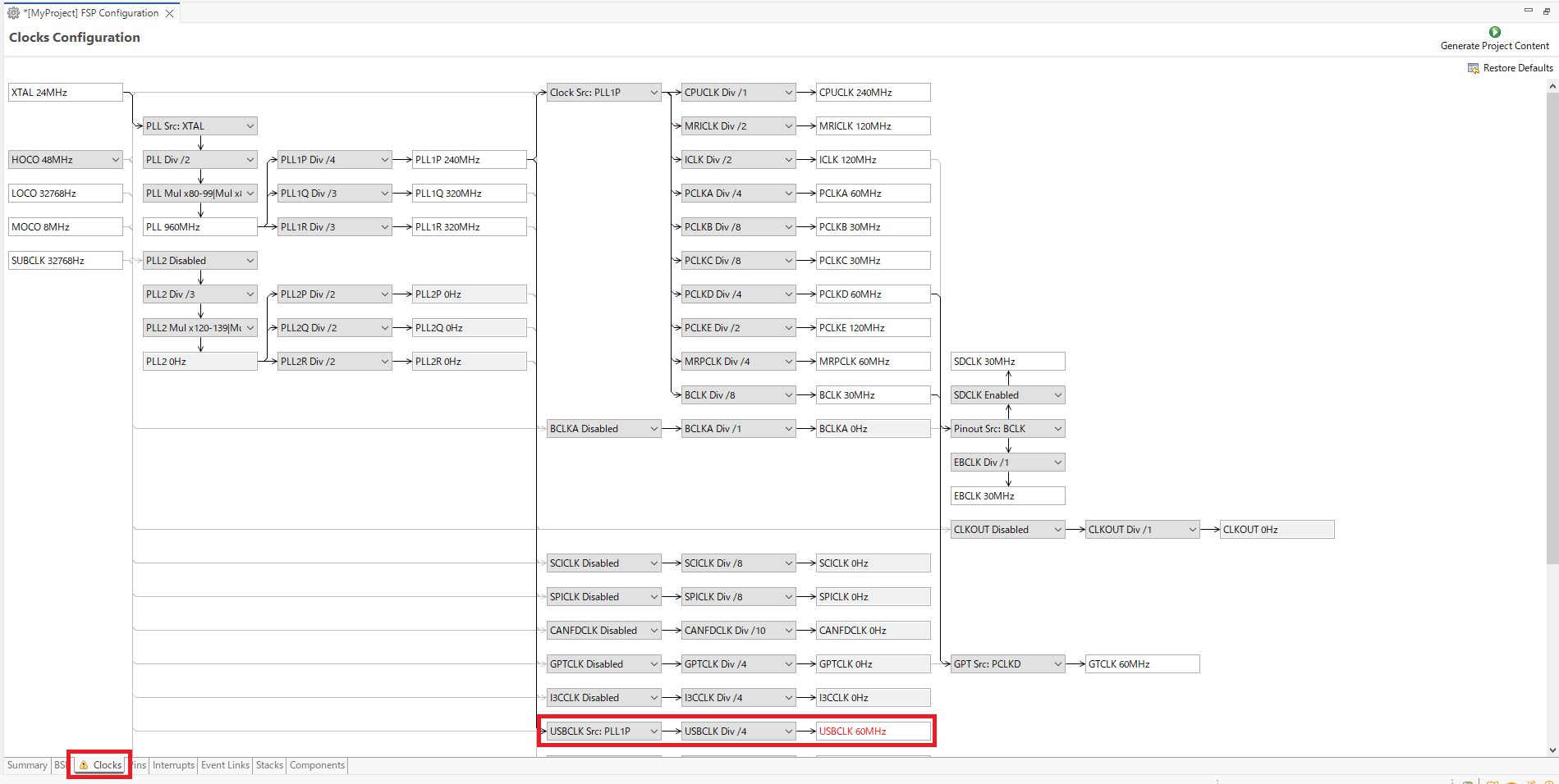
When you click the Generate Project Content button, the clock configuration contents are written to: rx_gen/bsp_clock_cfg.h
This file will be created if it does not already exist.
The Pins tab provides flexible configuration of the MCU's pins. As many pins are able to provide multiple functions, they can be configured on a peripheral basis. For example, selecting a serial channel via the SCI peripheral offers multiple options for the location of the receive and transmit pins for that module and channel. Once a pin is configured, it is shown as green in the Package view.
The Pins tab simplifies the configuration of large packages with highly multiplexed pins by highlighting errors and presenting the options for each pin or for each peripheral. If you selected a project template for a specific board such as the Renesas RX MCU Evaluation Kits, some peripherals connected on the board are preselected.
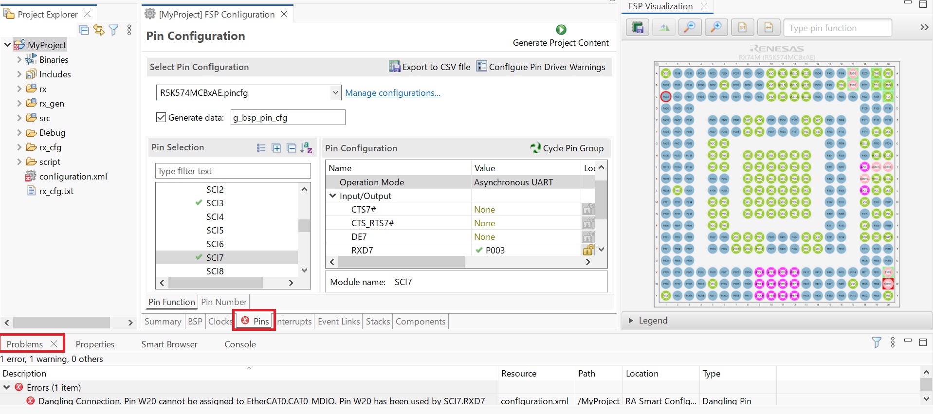
The pin configurator includes a built-in conflict checker, so if the same pin is allocated to another peripheral or I/O function the pin will be shown as red in the package view and also with white cross in a red square in the Pin Selection pane and Pin Configuration pane in the main Pins tab. The Pin Conflicts view provides a list of conflicts, so conflicts can be quickly identified and fixed.
In the example shown below, port P611 is already used by the CAC, and the attempt to connect this port to the Serial Communications Interface (SCI) results in a dangling connection error. To fix this error, select another port from the pin drop-down list or disable the CAC in the Pin Selection pane on the left side of the tab.
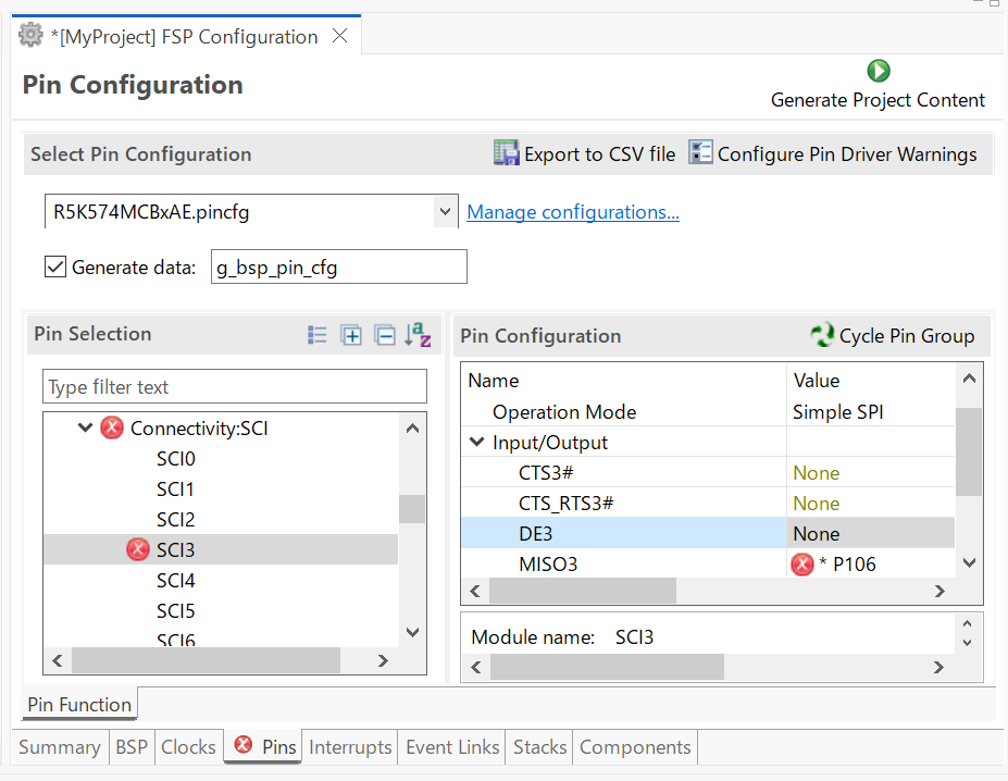
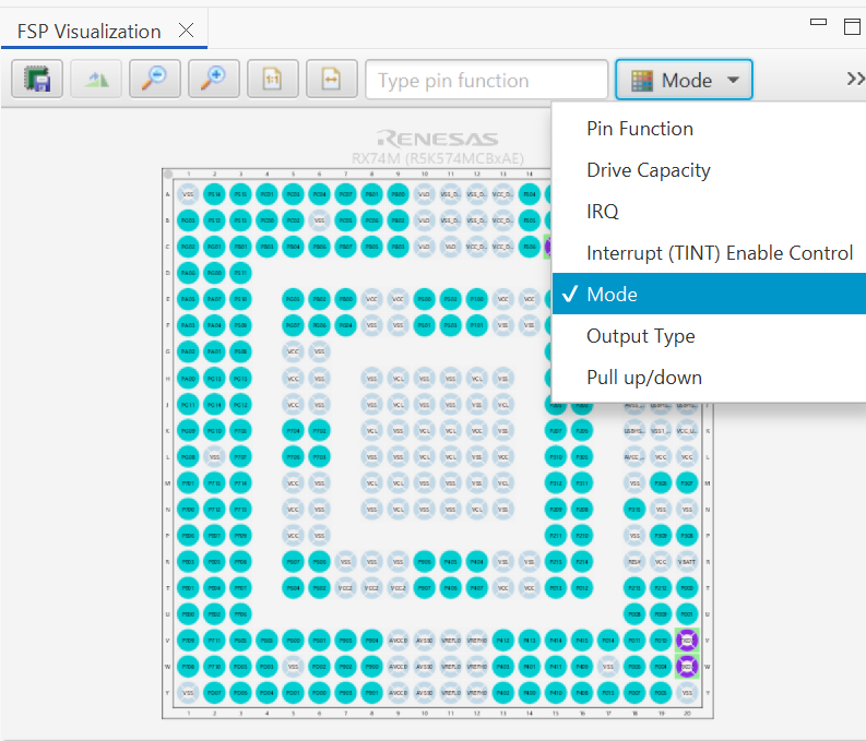
The pin configurator also shows a package view and the selected electrical or functional characteristics of each pin.
When you click the Generate Project Content button, the pin configuration contents are written to: rx_gen\bsp_pin_cfg.h
This file will be created if it does not already exist.
To make it easy to share pinning information for your project, e2 studio exports your pin configuration settings to a csv format and copies the csv file to rx_gen/<MCU package>.csv.
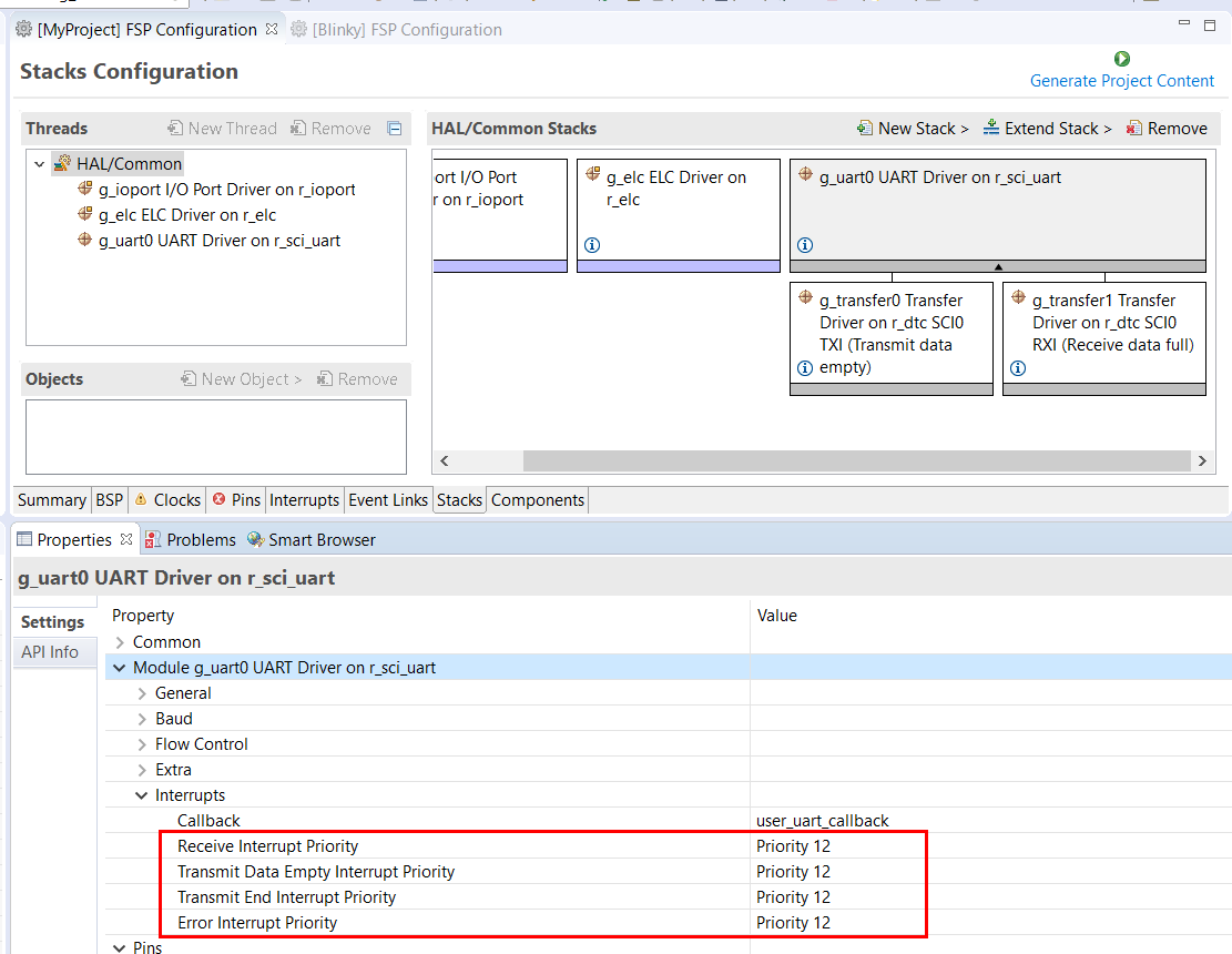
You can use the Properties view in the Stacks tab to enable interrupts by setting the interrupt priority. Select the driver in the Stacks pane to view and edit its properties.
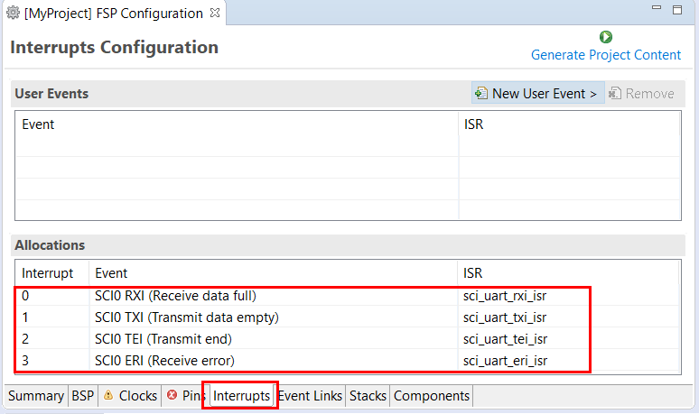
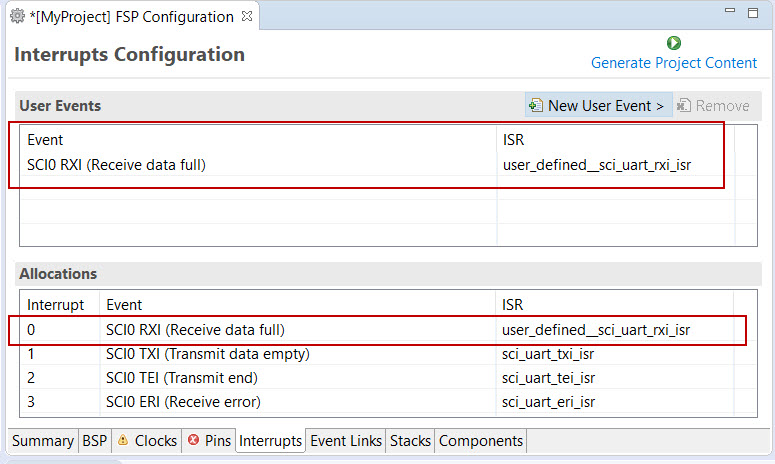
On the Interrupts tab, the user can bypass a peripheral interrupt set by the FSP by setting a user-defined ISR. This can be done by adding a new event via the New User Event button.
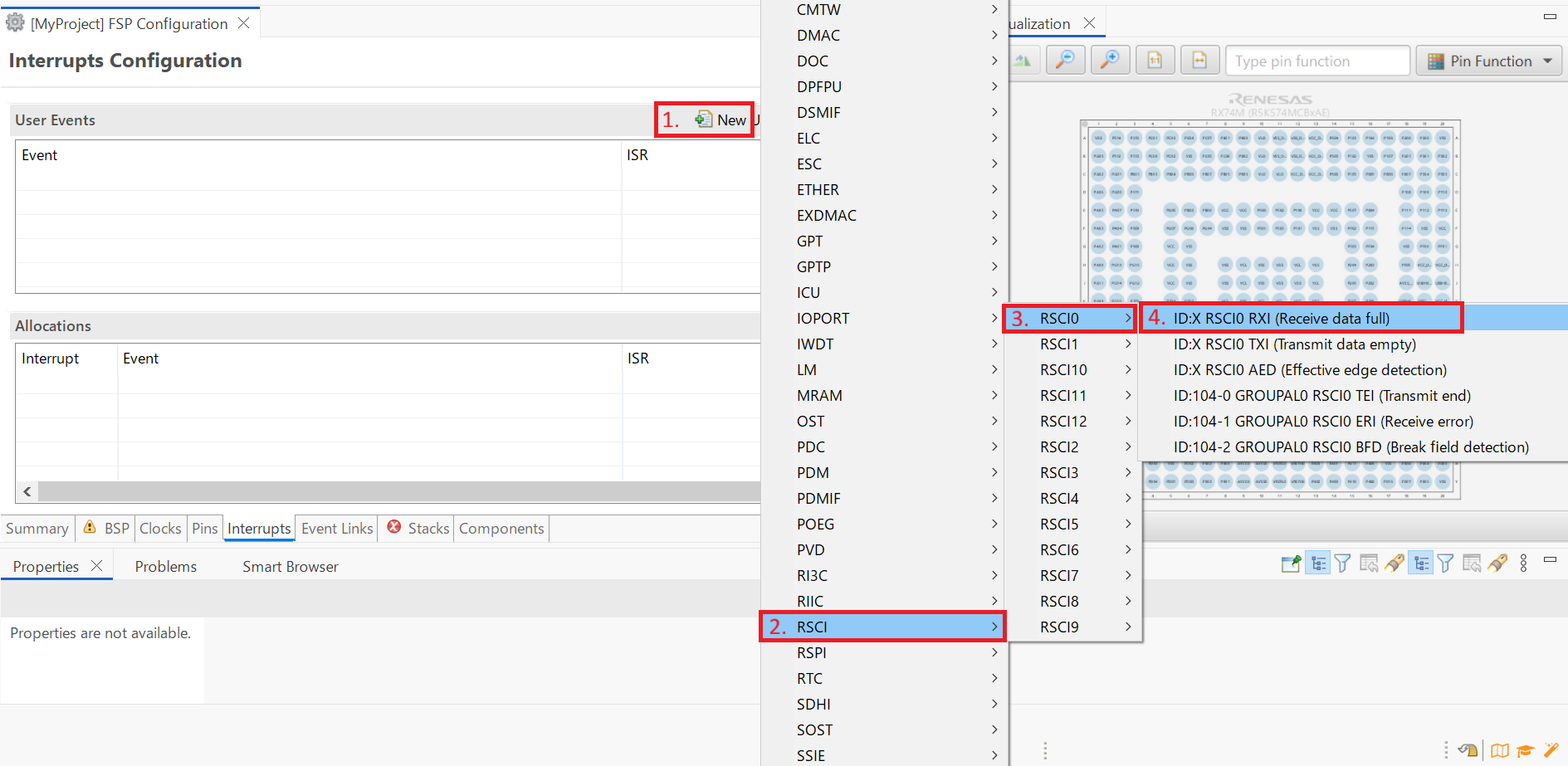
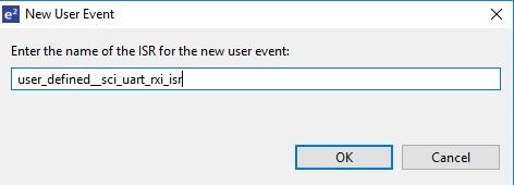
Enter the name of ISR for the new user event.
The Event Links tab can be used to view the Event Link Controller events. The events are sorted by peripheral to make it easy to find and verify them.
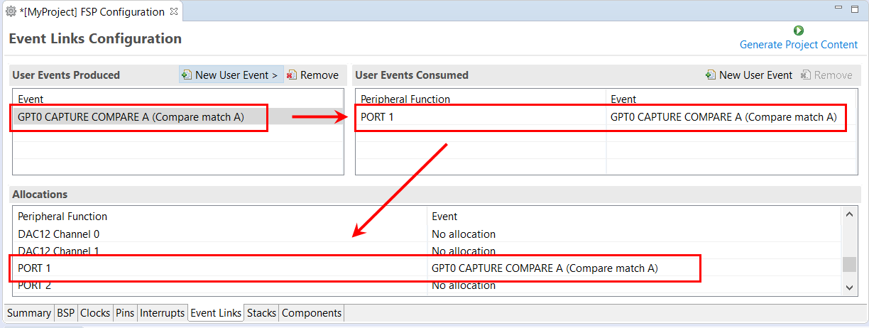
Like the Interrupts tab, user-defined event sources and destinations (producers and consumers) can be defined by clicking the relevant New User Event button. Once a consumer is linked to a producer the link will appear in the Allocations section at the bottom.
Every RTOS-based RX Project includes at least one RTOS Thread and a stack of FSP modules running in that thread. The Stacks tab is a graphical user interface which helps you to add the right modules to a thread and configure the properties of both the threads and the modules associated with each thread. Once you have configured the thread, e2 studio automatically generates the code reflecting your configuration choices.
For any driver, or, more generally, any module that you add to a thread, e2 studio automatically resolves all dependencies with other modules and creates the appropriate stack. This stack is displayed in the Stacks pane, which e2 studio populates with the selected modules and module options for the selected thread.
The default view of the Stacks tab includes a Common Thread called HAL/Common. This thread includes the driver for I/O control (IOPORT). The default stack is shown in the HAL/Common Stacks pane. The default modules added to the HAL/Common driver are special in that the FSP only requires a single instance of each, which e2 studio then includes in every user-defined thread by default.
In applications that do not use an RTOS or run outside of the RTOS, the HAL/Common thread becomes the default location where you can add additional drivers to your application.
For a detailed description on how to add and configure modules and stacks, see the following sections:
Once you have added a module either to HAL/Common or to a new thread, you can access the driver's configuration options in the Properties view. If you added thread objects, you can access the objects configuration options in the Properties view in the same way.
You can find details about how to configure threads here: Configuring Threads
For applications that run outside or without the RTOS, you can add additional HAL drivers to your application using the HAL/Common thread. To add drivers, follow these steps:
Click on the HAL/Common icon in the Stacks pane. The Modules pane changes to HAL/Common Stacks.
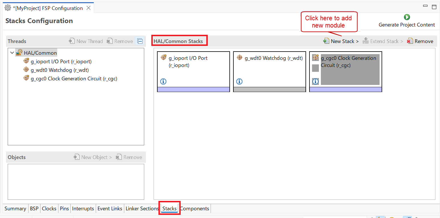
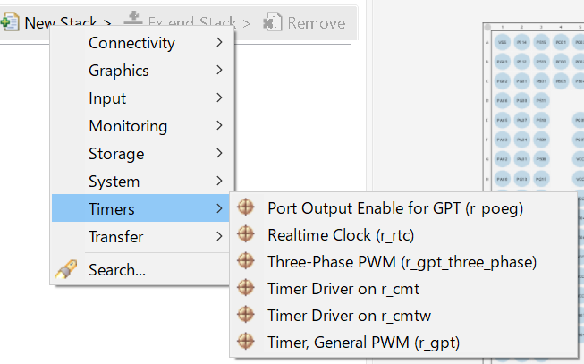
Select a driver from the menu New Stack > Driver.
e2 studio adds the following files when you click the Generate Project Content button:
rx/fsp directorymain() function and configuration structures and header files for your application as shown in the table below.| File | Contents | Overwritten by Generate Project Content? |
|---|---|---|
| rx_gen/main.c | Contains main() calling generated and user code. When called, the BSP already has Initialized the MCU. | Yes |
| rx_gen/hal_data.c | Configuration structures for HAL Driver only modules. | Yes |
| rx_gen/hal_data.h | Header file for HAL driver only modules. | Yes |
| src/hal_entry.c | User entry point for HAL Driver only code. Add your code here. | No |
The configuration header files for all included modules are created or overwritten in this folder: rx_cfg/fsp_cfg
For an application that uses the RTOS, you can add one or more threads, and for each thread at least one module that runs in the thread. You can select modules from the Driver dropdown menu. To add modules to a thread, follow these steps:
In the Threads pane, click New Thread to add a Thread.
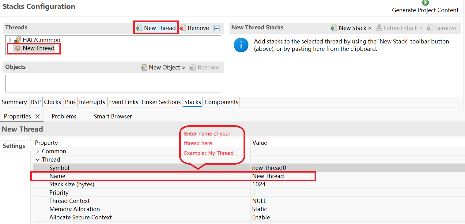
In the Properties view, click on the Name and Symbol entries and enter a distinctive name and symbol for the new thread.
In the My Thread Stacks pane, click on New Stack to see a list of modules and drivers. HAL-level drivers can be added here.
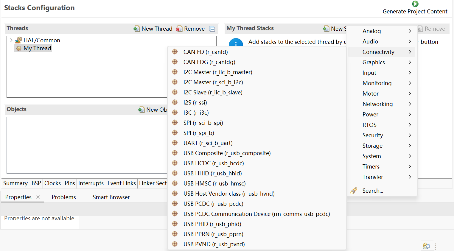
Click on the added driver and configure the driver as required by the application by updating the configuration parameters in the Properties view. To see the selected module or driver and be able to edit its properties, make sure the Thread containing the driver is highlighted in the Threads pane.
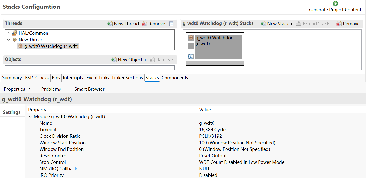
When you press the Generate Project Content button for the example above, e2 studio creates the files as shown in the following table:
| File | Contents | Overwritten by Generate Project Content? |
|---|---|---|
| rx_gen/main.c | Contains main() calling generated and user code. When called the BSP will have initialized the MCU. | Yes |
| rx_gen/my_thread.c | Generated thread "my_thread" and configuration structures for modules added to this thread. | Yes |
| rx_gen/my_thread.h | Header file for thread "my_thread" | Yes |
| rx_gen/hal_data.c | Configuration structures for HAL Driver only modules. | Yes |
| rx_gen/hal_data.h | Header file for HAL Driver only modules. | Yes |
| src/hal_entry.c | User entry point for HAL Driver only code. Add your code here. | No |
| src/my_thread_entry.c | User entry point for thread "my_thread". Add your code here. | No |
The configuration header files for all included modules and drivers are created or overwritten in the following folders: rx_cfg/fsp_cfg/<header files>
If the application uses an RTOS, the Stacks tab can be used to simplify the creation of RTOS threads, semaphores, mutexes, and event flags.
The components of each thread can be configured from the Properties view as shown below.
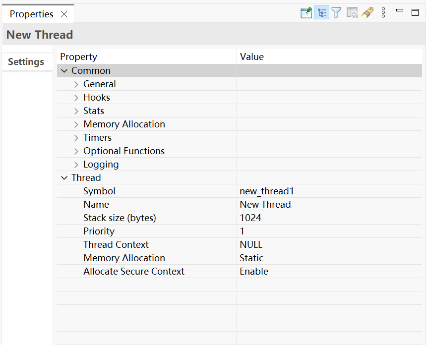
The Properties view contains settings common for all Threads (Common) and settings for this particular thread (Thread).
For this thread instance, the thread's name and properties (such as priority level or stack size) can be easily configured. e2 studio checks that the entries in the property field are valid. For example, it will verify that the field Priority, which requires an integer value, only contains numeric values between 0 and 9.
To add RTOS resources to a Thread, select a thread and click on New Object in the Thread Objects pane. The pane takes on the name of the selected thread, in this case My Thread Objects.
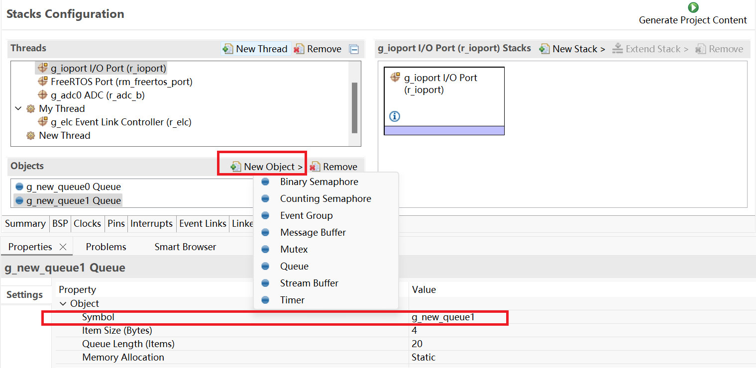
Make sure to give each thread object a unique name and symbol by updating the Name and Symbol entries in the Properties view.
The Components tab enables the individual modules required by the application to be included or excluded. Modules common to all RX MCU projects are preselected (for example: BSP > BSP > Board-specific BSP and HAL Drivers > all > r_cgc). All modules that are necessary for the modules selected in the Stacks tab are included automatically. You can include or exclude additional modules by ticking the box next to the required component.
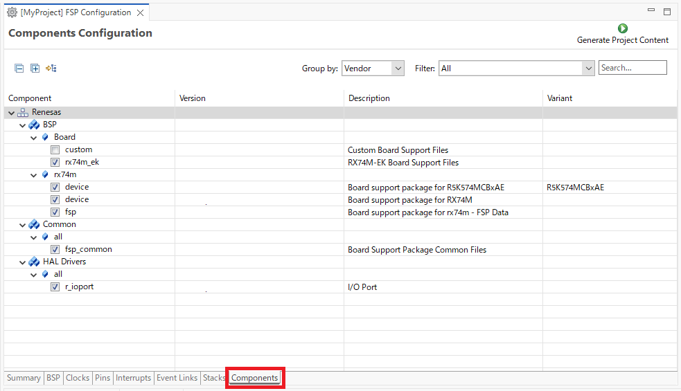
Clicking the Generate Project Content button copies the .c and .h files for each selected component into the following folders:
rx/fsp/inc/apirx/fsp/inc/instancesrx/fsp/src/bsprx/fsp/src/<Driver_Name>e2 studio also creates configuration files in the rx_cfg/fsp_cfg folder with configuration options set in the Stacks tab.
Once you have added Modules and drivers and set their configuration parameters in the Stacks tab, you can add the application code that calls the Modules and drivers.
e2 studio provides several efficiency improving features that help write code. Review these features prior to digging into the code development step-by-step sections that follow.
Autocomplete is a context aware coding accelerator that suggests possible completions for partially typed-in code elements. If you can 'guess' the first part of a macro, for example, the Autocomplete function can suggest options for completing the rest of the macro.
In the following example, a macro related to a BSP_IO setting needs to be found. After typing BSP_IO_ in a source code file, pressing Ctrl + Space opens the Autocomplete list. This list shows a selection of context aware options for completing the macro. Scroll through the window to find the desired macro (in this case BSP_IO_LEVEL_HIGH) and click on it to add it to your code.
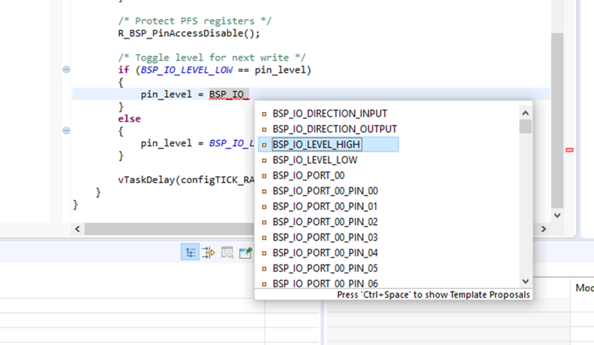
Other code elements can use autocomplete too. Some of the more common uses for Autocomplete include Enumerations, Types, and API functions - but try it in any situation you think the tool may have enough context to determine what you might be looking for.
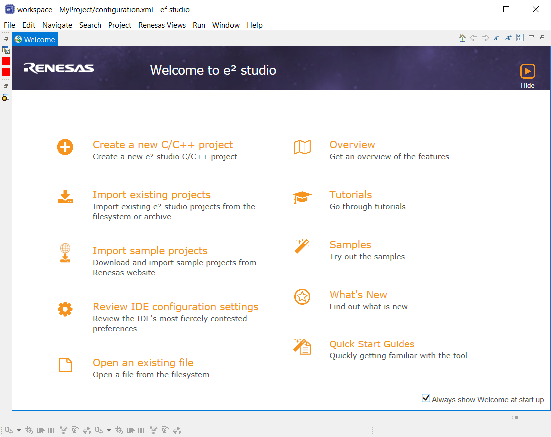
The e2 studio Welcome window displays useful information and common links to assist in development. Check out these resources to see what is available. They are updated with each release, so check back to see what has been added after a new release.
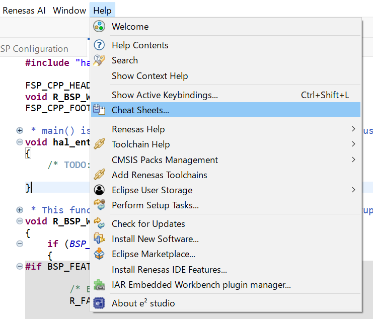
Cheat sheets are macro driven illustrations of some common tasks. They show, step-by-step, what commands and menus are used. These will be populated with more examples on each release. Cheat Sheets are available from the Help menu.
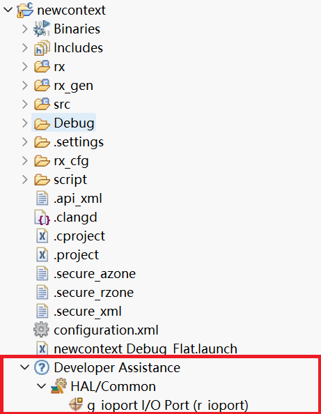
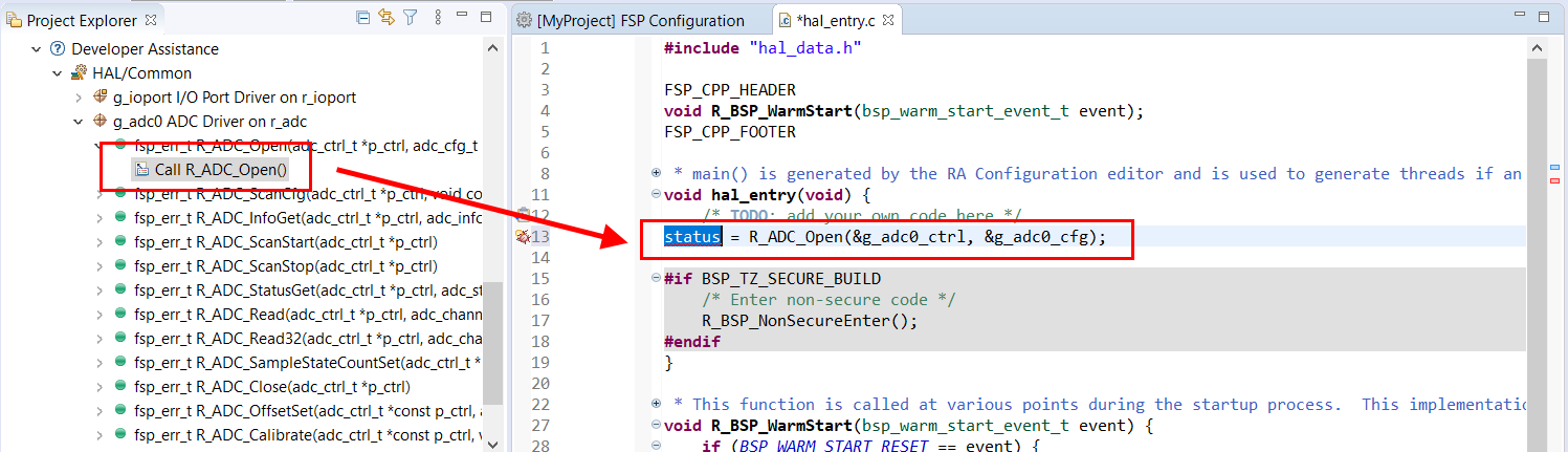
FSP Developer Assistance provides developers with module and Application Programming Interface (API) reference documentation in e2 studio. After configuring the threads and software stacks for an FSP project with the FSP Configuration editor, Developer Assistance quickly helps you get started writing C/C++ application code for the project using the configured stack modules.
Expand the project explorer to view Developer Assistance
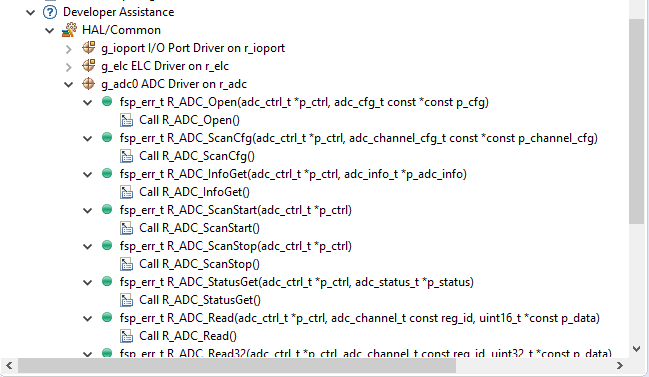
Expand a stack module to show its APIs
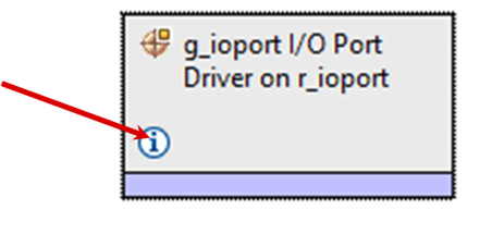
Information icons are available on each module in the thread stack. Clicking on these icons opens a module folder on GitHub that contains additional information on the module. An example information Icon is shown below:
A good source of additional information for many FSP topics is the Help system. To get to the Help system, click on Help and then select Help Contents as seen below.
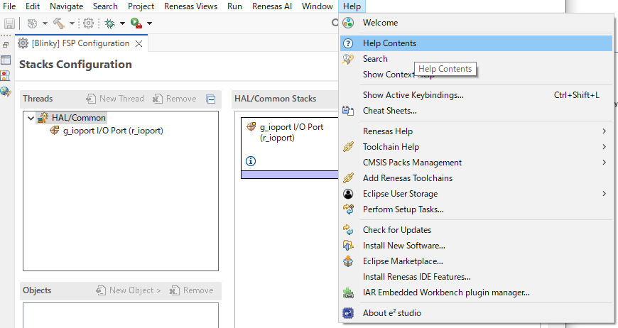
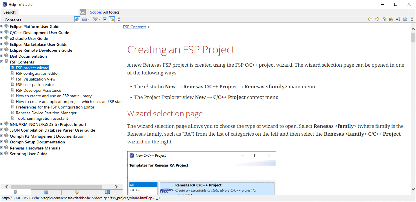
Once the Help system is open, select the FSP Contents entry in the left side Guide-bar. Expand it to see the main FSP Topics.
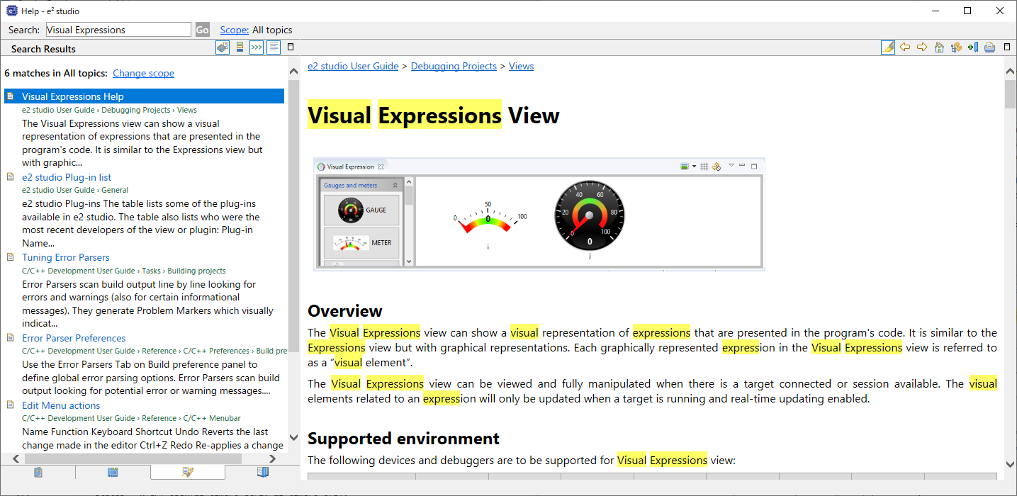
You can also search for help topics by using the Search bar. Below is an example searching for Visual Expressions, a helpful feature in the e2 studio debugger.
The FSP Architecture section describes FSP stacks, modules and interfaces in significant detail, providing an understanding of the theory behind them. The following sections provides a quick and practical introduction on how to use API functions when writing code and where in the API reference sections you can find useful API related information.
In FSP, HAL module drivers provide convenient API functions that access RX processor peripheral features. Module properties are defined in the RX GUI configurator, eliminating the tedious and error prone process of setting peripheral control registers. When configuration is complete, the generator automatically creates the code needed to implement the associated API functions. API functions are the main way a developer interacts with the target processor and peripherals.
HAL driver API functions all have a similar format. They all start with "R_" to indicate they are HAL related functions. Next comes the module name followed by the function and any parameters. This format is illustrated below:
Here are some examples:
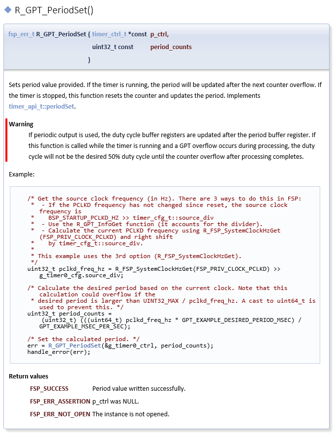
Each HAL module has a useful API Reference section that includes key details on each function. The function prototype is presented first, showing the return type (usually fsp_status_t for HAL functions) and the function parameters. A short description and any warnings or notes follow the function definition. In some cases, a code snippet is included to illustrate use of the function. Finally, all possible return values are provided to assist in debugging and error management.
To write application code:
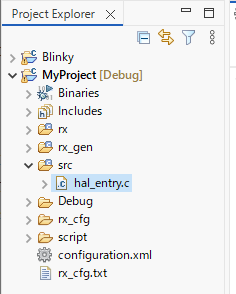
In the Project Explorer view, double-click on the src/hal_entry.c file to edit the source file.
rx_gen/hal_data.c.Add your application code here:
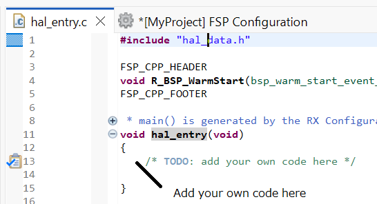
The following tutorial shows how execute the steps above and add application code: Tutorial: Using HAL Drivers - Programming the WDT.
The WDT example is a HAL level application which does not use an RTOS.
The user guides for each module also include basic application code that you can add to hal_entry.c.
To write RTOS-aware application code using RTOS, follow these steps:
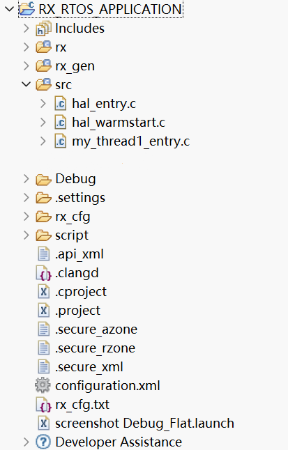
In the Project Explorer view, double-click on the src/my_thread_1_entry.c file to edit the source file.
rx_gen/my_thread_1.c and my_thread_2.crx_gen. These files are overwritten every time you push the Generate Project Content button.Add your application code here:
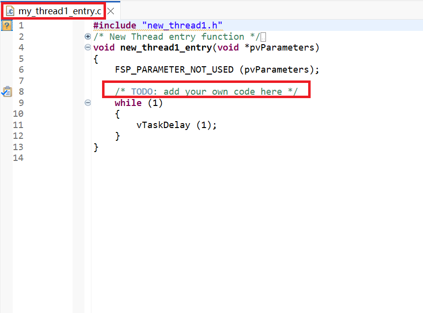
Once your project builds without errors, you can use the Debugger to download your application to the board and execute it.
To debug an application follow these steps:
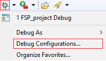
On the drop-down list next to the debug icon, select Debug Configurations.
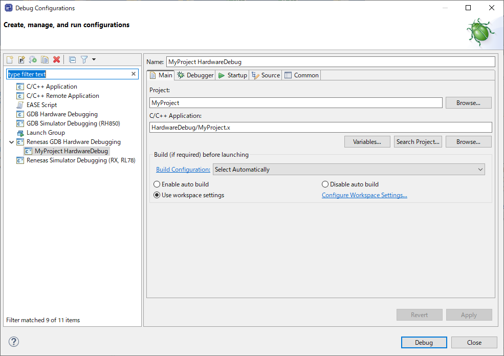
In the Debug Configurations view, click on your project listed as MyProject Debug.
There are instances where it may be necessary to make changes to the toolchain being used (for example, to change optimization level of the compiler or add a library to the linker). Such modifications can be made from within e2 studio through the menu Project > Properties > C/C++ Build > Settings when the project is selected. The following screenshot shows the settings dialog for the GCC for Renesas RX toolchain. This dialog will look slightly different depending upon the toolchain being used.
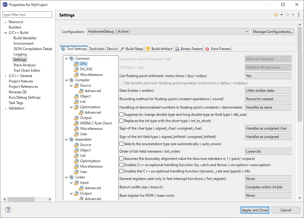
The scope for the settings is project scope which means that the settings are valid only for the project being modified.
The settings for the linker which control the location of the various memory sections are contained in a script file specific for the device being used. This script file is included in the project when it is created and is found in the script folder (for example, /script/rx/fsp.ld).
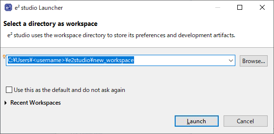
At the end of e2 studio startup, you will see the Workspace Launcher Dialog box as shown in the following figure.
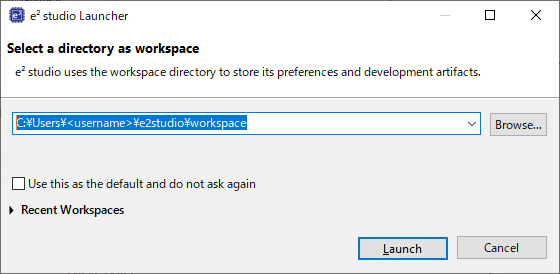
Enter a new workspace name in the Workspace Launcher Dialog as shown in the following figure. e2 studio creates a new workspace with this name.
When the workspace is opened, you may see the Welcome Window. Click on the Workbench arrow button to proceed past the Welcome Screen as seen in the following figure.

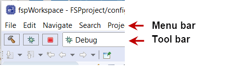
You are now in the workspace that you want to import the project into. Click the File menu in the menu bar, as shown in the following figure.
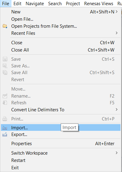
Click Import on the File menu or in the menu bar, as shown in the following figure.
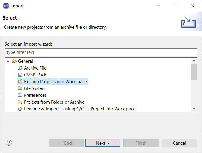
In the Import dialog box, as shown in the following figure, choose the General option, then Existing Projects into Workspace, to import the project into the current workspace.
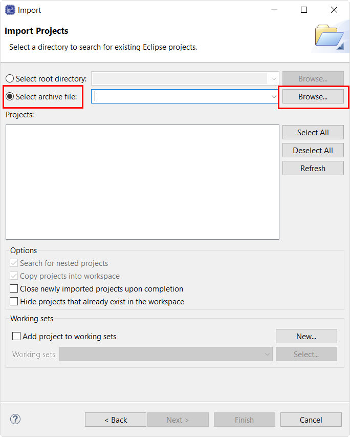
Click Select archive file as shown in the following figure.
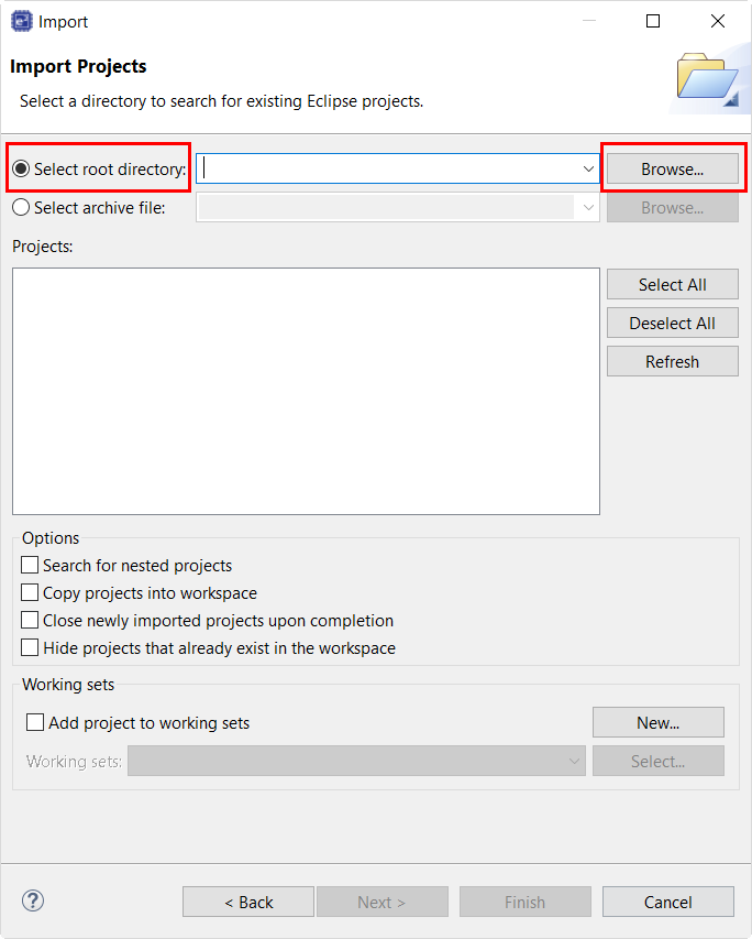
Click Select root directory as shown in the following figure.
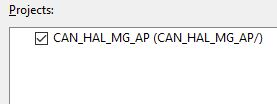
CAN_HAL_MG_AP.zip or CAN_HAL_MG_AP.Select the project to import from the list of Projects, as shown in the following figure.
The goal of this tutorial is to quickly get acquainted with the Flexible Platform by moving through the steps of creating a simple application using e² studio and running that application on an RX MCU board.
The application used in this tutorial is Blinky, traditionally the first program run in a new embedded development environment.
Blinky is the "Hello World" of microcontrollers. If the LED blinks you know that:
The Blinky example application used in this tutorial is designed to run the same way on all boards offered by Renesas that hold the RX microcontroller. The code in Blinky is completely board independent. It does the work by calling into the BSP (board support package) for the particular board it is running on. This works because:
To follow this tutorial, you need:
The creation and configuration of a RX MCU project is the first step in the creation of an application. The base RX MCU pack includes a pre-written Blinky example application that is simple and works on all Renesas RX MCU boards.
Follow these steps to create an RX MCU project:
Click Next. The Project Configuration window shows your selection.
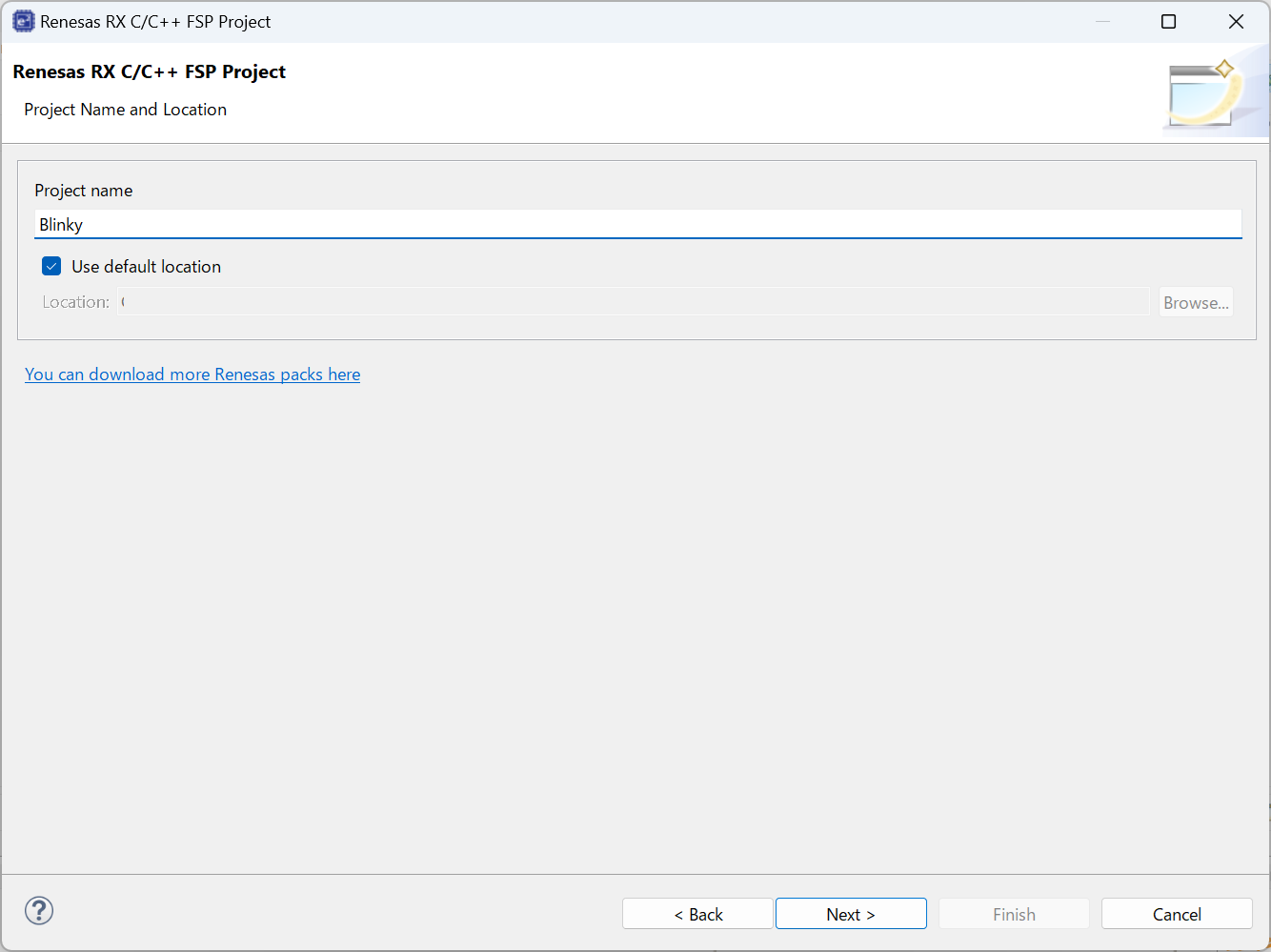
Select the board support package by selecting the name of your board from the Device Selection drop-down list and click Next.
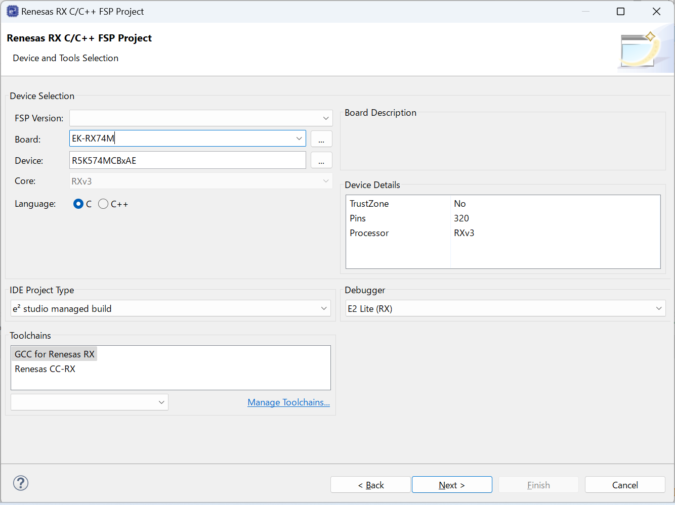
Select the build artifact and RTOS.
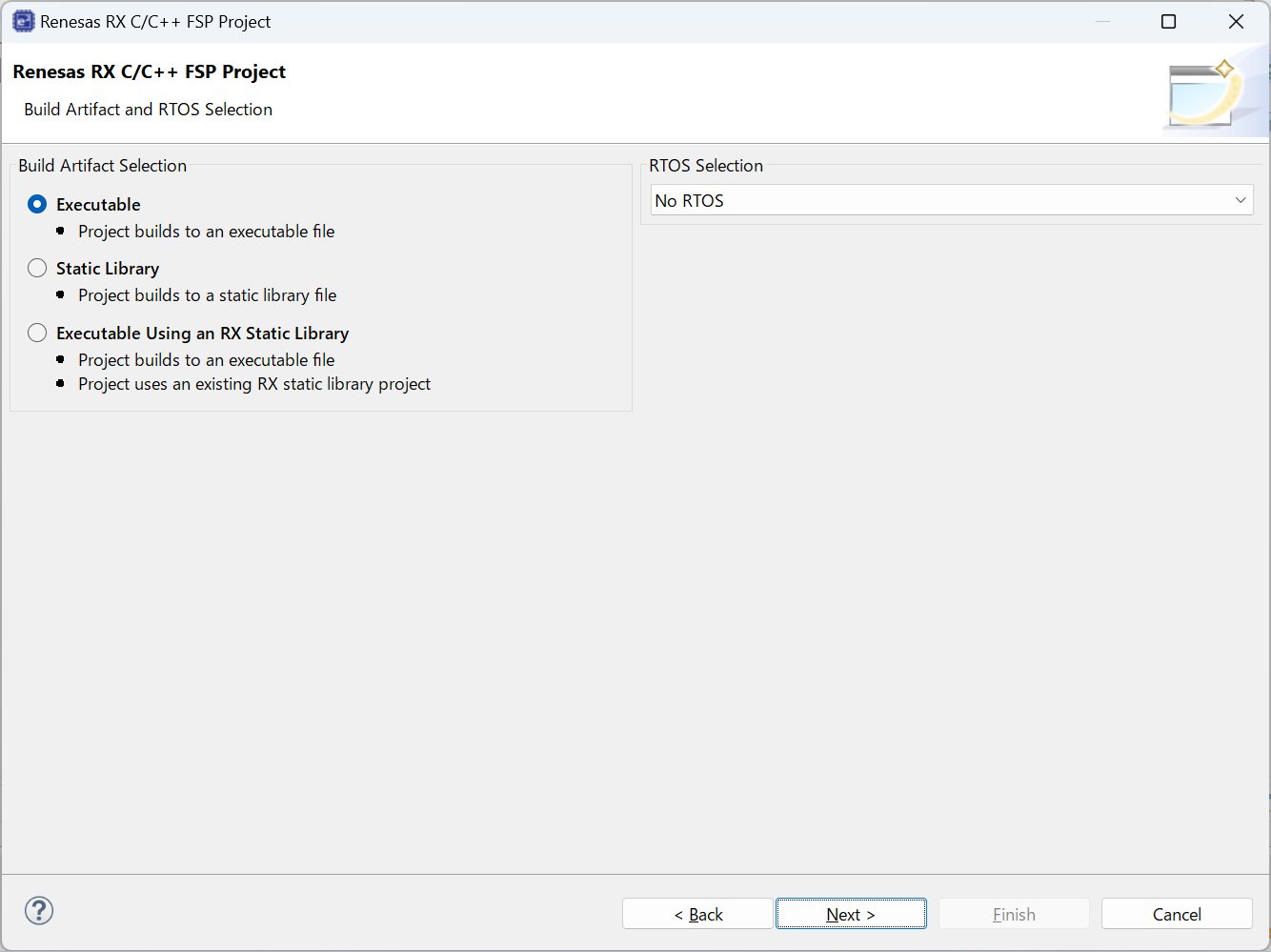
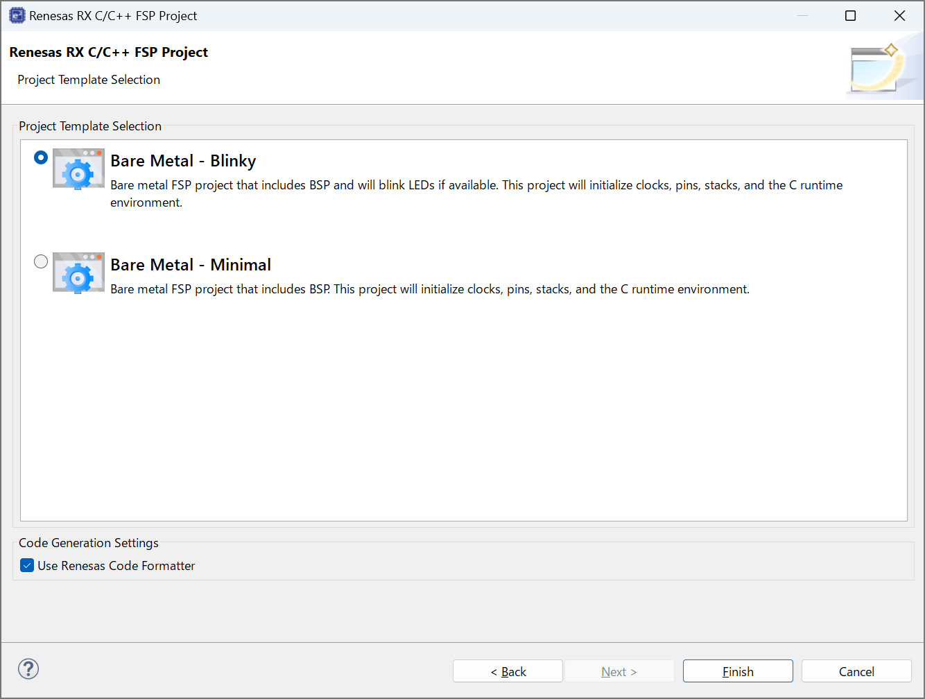
Select the Blinky template for your board and click Finish.
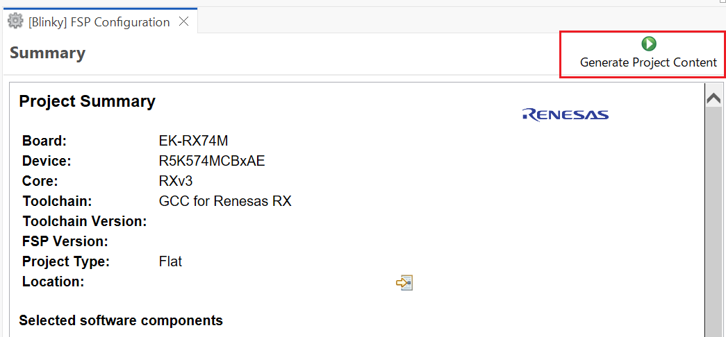
Once the project has been created, the name of the project will show up in the Project Explorer window of e² studio. Now click the Generate Project Content button in the top right corner of the Project Configuration window to generate your board specific files.
Your new project is now created, configured, and ready to build.
The Generate Project Content button creates configuration header files, copies source files from templates, and generally configures the project based on the state of the Project Configuration screen.
For example, if you check a box next to a module in the Components tab and click the Generate Project Content button, all the files necessary for the inclusion of that module into the project will be copied or created. If that same check box is then unchecked those files will be deleted.
By selecting the Blinky template, the clocks are configured by e² studio for the Blinky application. The clock configuration tab (see Configuring Clocks) shows the Blinky clock configuration. The Blinky clock configuration is stored in the BSP clock configuration file (see BSP Clock Configuration).
By selecting the Blinky template, the GPIO pins used to toggle the LED1 are configured by e² studio for the Blinky application. The pin configuration tab shows the pin configuration for the Blinky application (see Configuring Pins). The Blinky pin configuration is stored in the BSP configuration file (see BSP Pin Configuration).
The Blinky project automatically selects the following HAL components in the Components tab:
To see the configuration parameters for any of the components, check the Properties tab in the HAL window for the respective driver (see Adding and Configuring HAL Drivers).
The main function is located in < project >/rx_gen/main.c. It is one of the files that are generated during the project creation stage and only contains a call to hal_entry(). For more information on generated files, see Adding and Configuring HAL Drivers.
The blinky application is stored in the hal_entry.c file. This file is generated by e² studio when you select the Blinky Project template and is located in the project's src/ folder.
The application performs the following steps:
R_BSP_PinWrite((bsp_io_port_pin_t) pin, pin_level);Highlight the new project in the Project Explorer window by clicking on it and build it.
There are three ways to build a project:
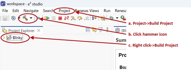
Once the build is complete a message is displayed in the build Console window that displays the final image file name and section sizes in that image.
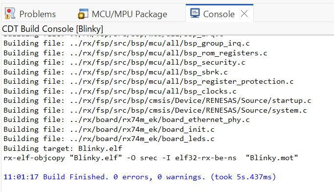
To debug the project on a board, you need
Applications run from the internal flash of your microcontroller. To run or debug the application, the application must first be programmed to the microcontroller's flash. There are two ways to do this:
Some boards have an on-board JTAG debugger and others require an external JTAG debugger connected to a header on the board.
Refer to your board's user manual to learn how to connect the JTAG debugger to e² studio.
To debug the Blinky application, follow these steps:
Configure the debugger for your project by clicking Run > Debugger Configurations ...
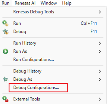
or by selecting the drop-down menu next to the bug icon and selecting Debugger Configurations ...
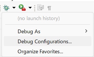
Select your debugger configuration in the window. If it is not visible then it must be created by clicking the New icon in the top left corner of the window. Once selected, the Debug Configuration window displays the Debug configuration for your Blinky project.
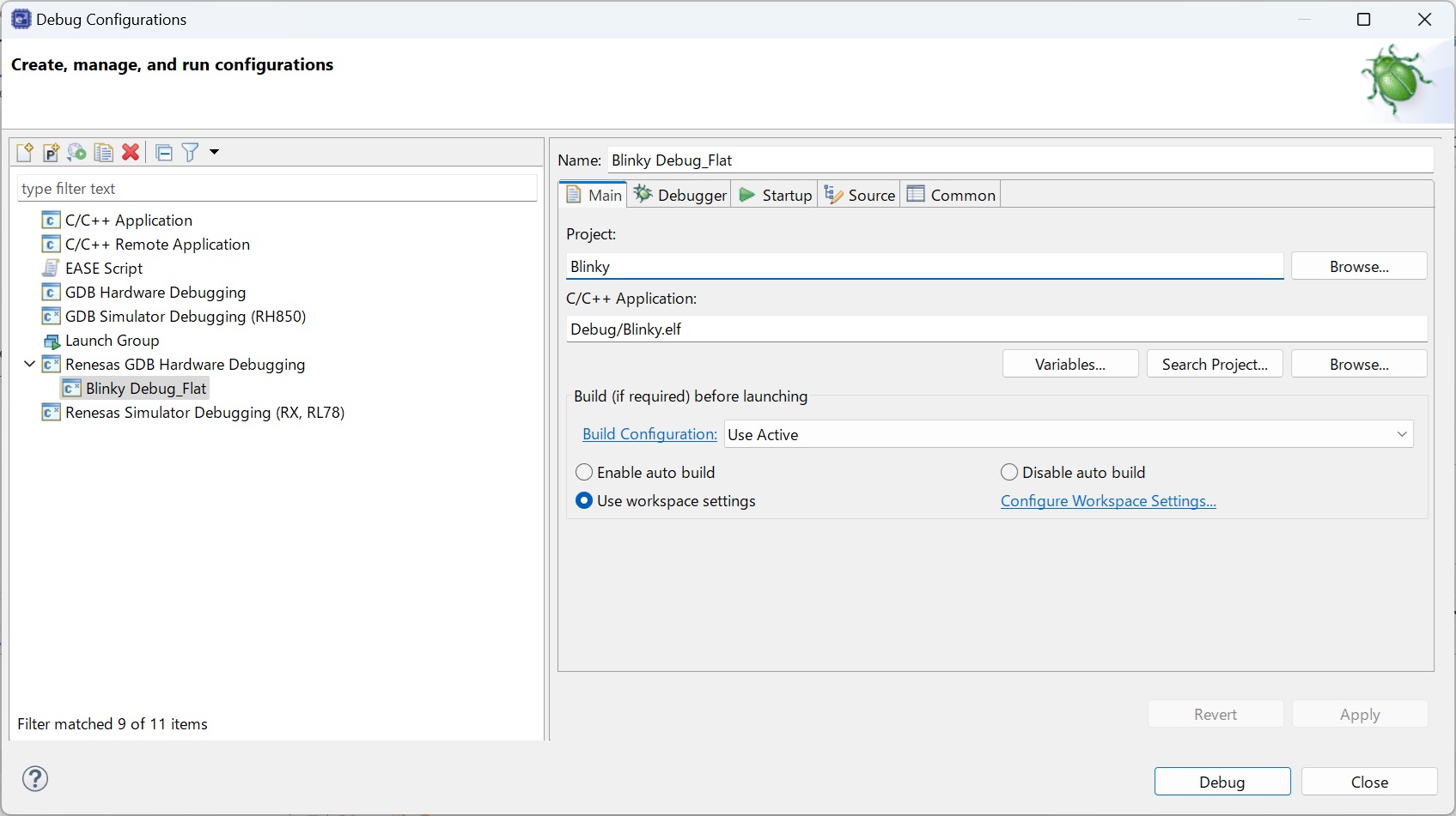
Extracting RX Debug.
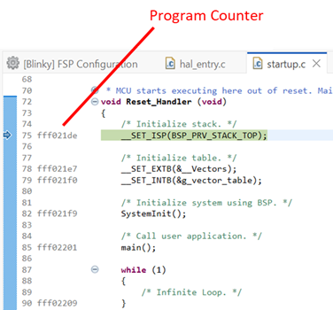
In debug mode, e² studio executes the following tasks:
While in Debug mode, click Run > Resume or click on the Play icon twice.

The LEDs on the board marked LED1, LED2, and LED3 should now be blinking.
This tutorial illustrates the creation of a simple application that uses the Watchdog Timer module to monitor program operation. The tutorial shows each step in the development process and in particular identifies the auto-generated files and project structure created when using FSP and its GUI based configurator. The level of detail provided here is more than is normally needed during development but can be helpful in explaining how FSP works behind the scenes to simplify your work.
This application makes use of the following FSP modules:
The Flexible Software Package (FSP) from Renesas provides a complete driver library for developing RX MCU applications. FSP provides Hardware Abstraction Layer (HAL) drivers, Board Support Package (BSP) drivers for the developer to use to create applications. FSP is integrated into Renesas e² studio based on eclipse providing build (editor, compiler and linker) and debug phases with an extended GNU Debug (GDB) interface.
The flowchart for the WDT application is shown below.
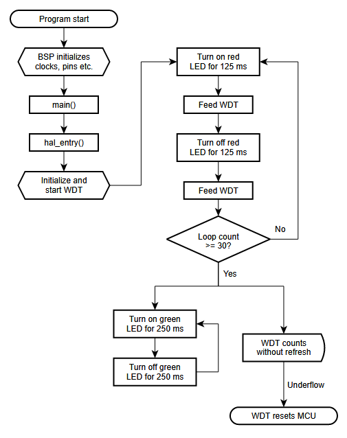
The main sections of the WDT application are:
main() calls hal_entry(). The function hal_entry() is created by FSP with a placeholder for user code. The code for the WDT is added to this function.Start e² studio and choose a workspace folder in the Workspace Launcher. Configure a new RX MCU project as follows.
Select File > New > RX C/C++ Project. Then select the template for the project.
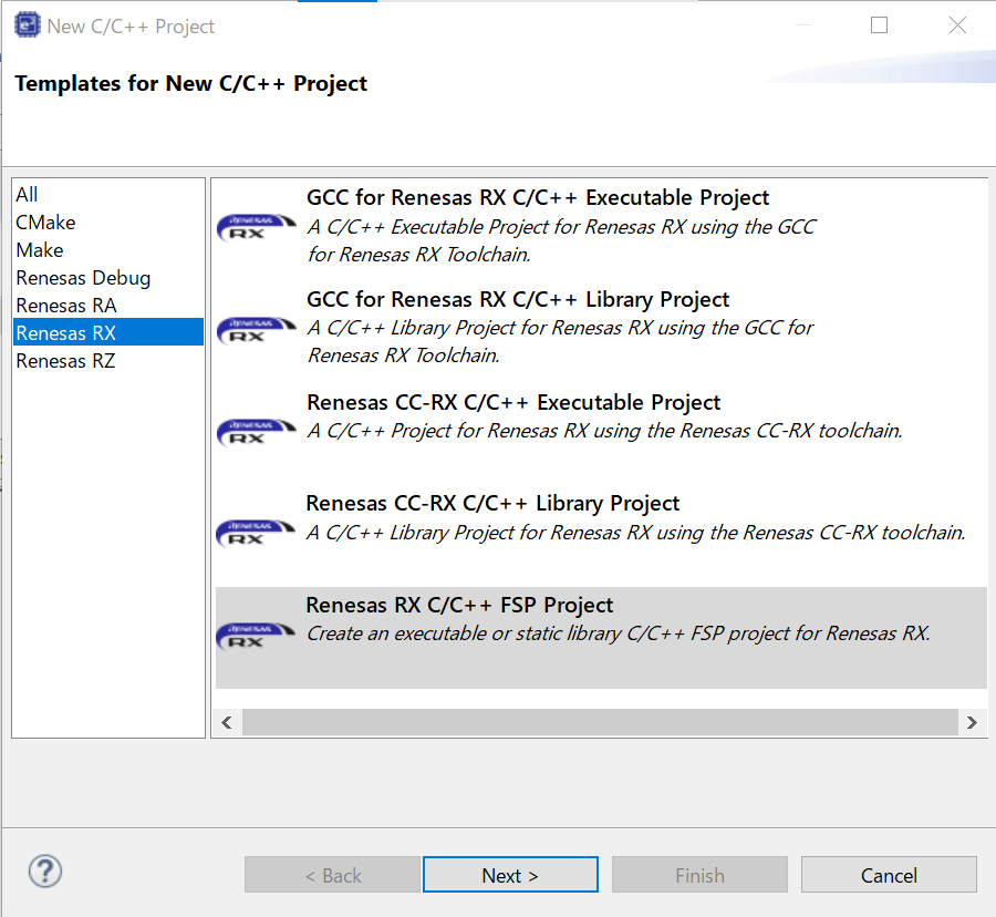
In the e² studio Project Configuration (RX Project) window enter a project name, for example, WDT_Application. In addition, select the toolchain. If you want to choose new locations for the project unselect Use default location. Click Next.
This application runs on the EK-RX74M board. So, for the Board select EK-RX74M.
This will automatically populate the Device drop-down with the correct device used on this board. Select the Toolchain version. Select E2 Lite as the Debugger. Click Next to configure the project.
This applicaiton runs without RTOS. So, for the RTOS selection select No RTOS. For the Build Artifact Selection select Excutable
The project template is now selected. As no RTOS is required select Bare Metal - Blinky.
Click Finish.
e² studio creates the project and opens the Project Explorer and Project Configuration Settings views with the Summary page showing a summary of the project configuration.
e² studio simplifies and accelerates the project configuration process by providing a GUI interface for selecting the options to configure the project.
e² studio offers a selection of perspectives presenting different windows to the user depending on the operation in progress. The default perspectives are C/C++, FSP Configuration and Debug. The perspective can be changed by selecting a new one from the buttons at the top right.

The C/C++ perspective provides a layout selected for code editing. The FSP Configuration perspective provides elements for configuring a RX MCU project, and the Debug perspective provides a view suited for debugging.
configuration.xml file in the Project Explorer pane on the right side of e² studio.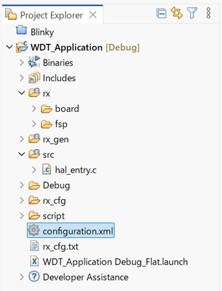
At the base of the Project Configuration view there are several tabs for configuring the project. A project may require changes to some or all of these tabs. The tabs are shown below.
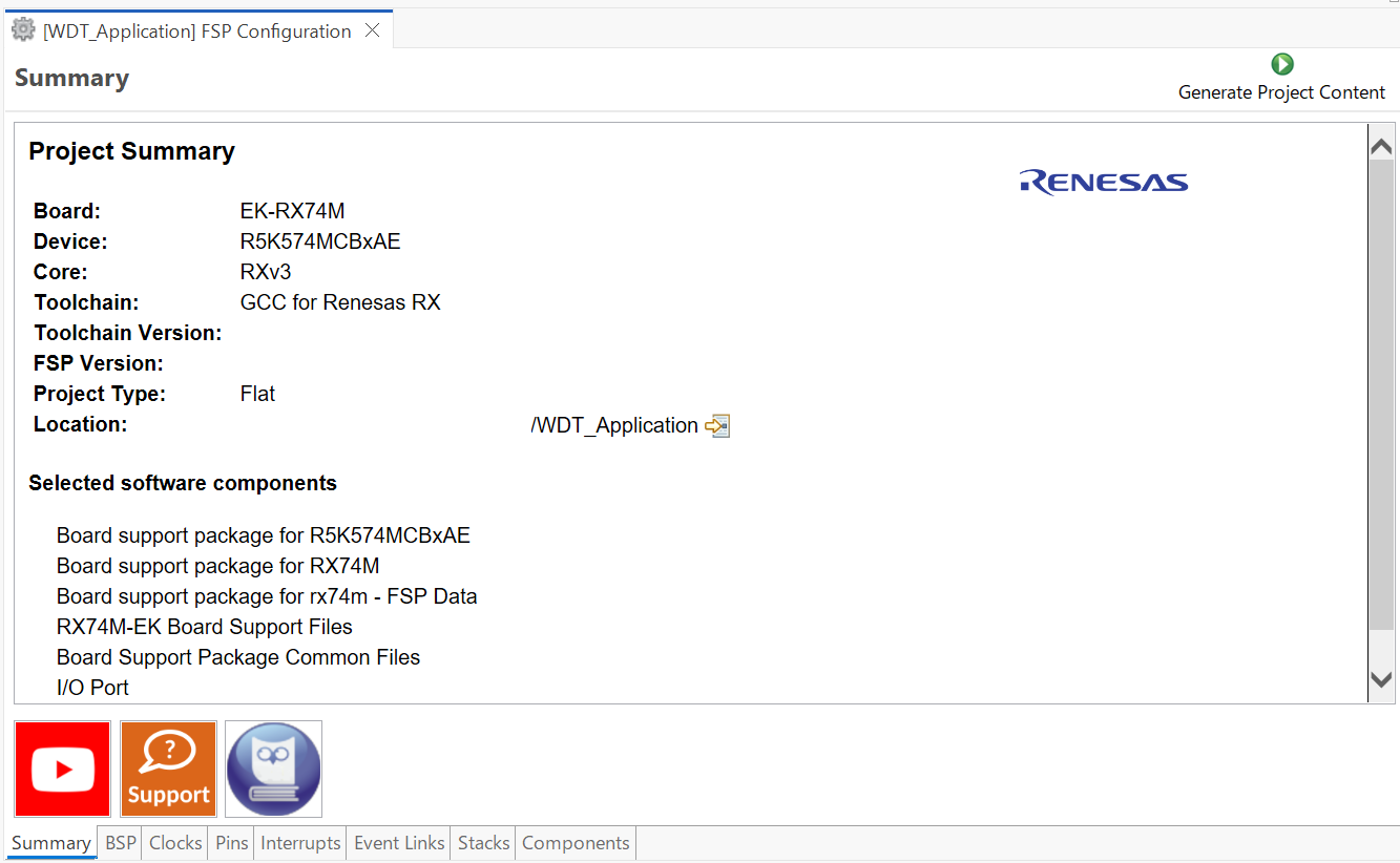
The BSP tab allows the Board Support Package (BSP) options to be modified from their defaults. For this particular WDT project no changes are required. However, if you want to use the WDT in auto-start mode, you can configure the settings of the OFS0 (Option Function Select Register 0) register in the BSP tab. See the RX Hardware User's Manual for details on the WDT autostart mode.
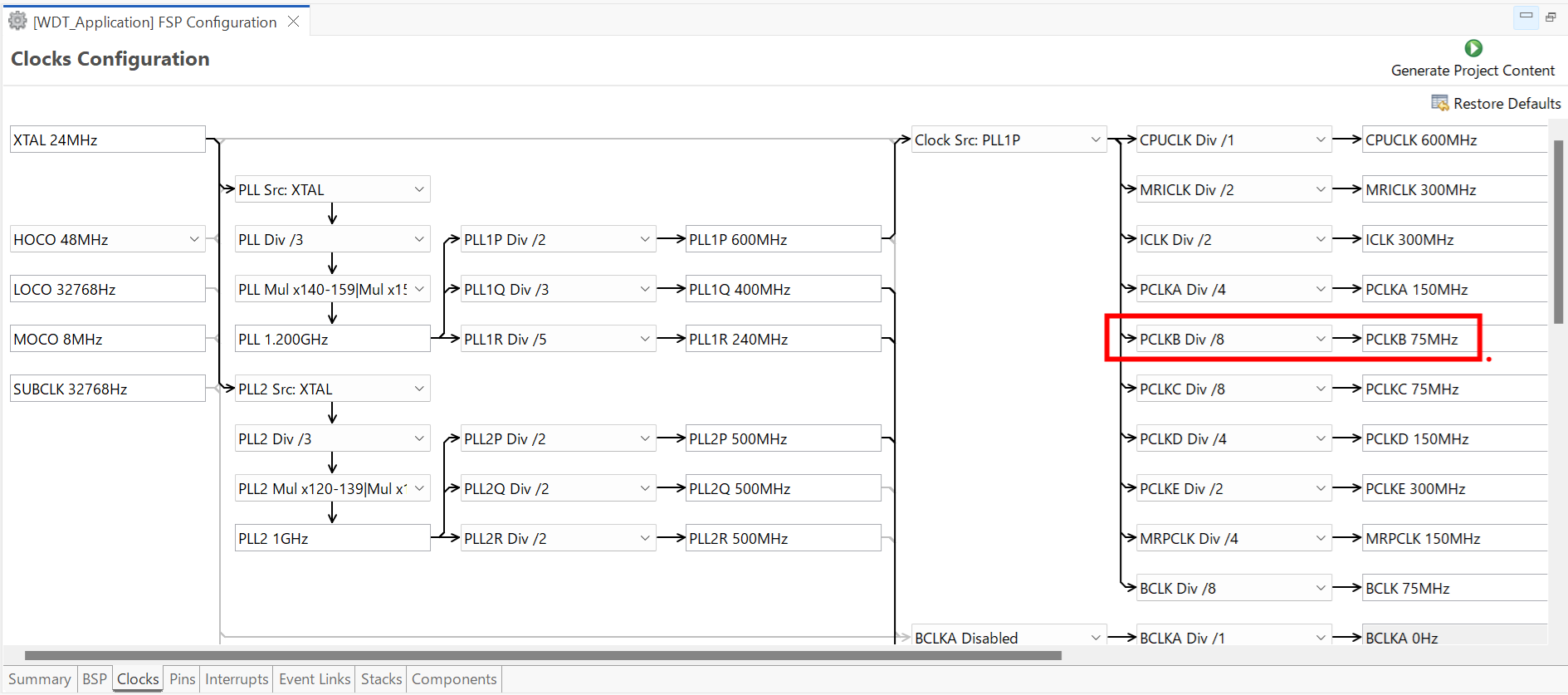
The Clocks tab presents a graphical view of the clock tree of the device. The drop-down boxes in the GUI enables configuration of the various clocks. The WDT uses PCLKB. The default output frequency for this clock is 75 MHz. Ensure this clock is outputting this value.
The Interrupts tab is used to add new user events or interrupts. No new interrupts or events are needed by the application, so no edits in this tab are required.
The Event Links tab is used to configure events used by the Event Link Controller (ELC). This project doesn't use the ELC, so no edits in this tab are required.
The Pins tab provides a graphical tool for configuring the functionality of the pins of the device. For the WDT project no pin configuration is required. Although the project uses two LEDs connected to pins on the device, these pins are pre-configured as output GPIO pins by the BSP.
You can add any driver to the project using the Stacks tab. The HAL driver IO port pins are added automatically by e² studio when the project is configured. The WDT application uses no RTOS Resources, so you only need to add the HAL WDT driver.
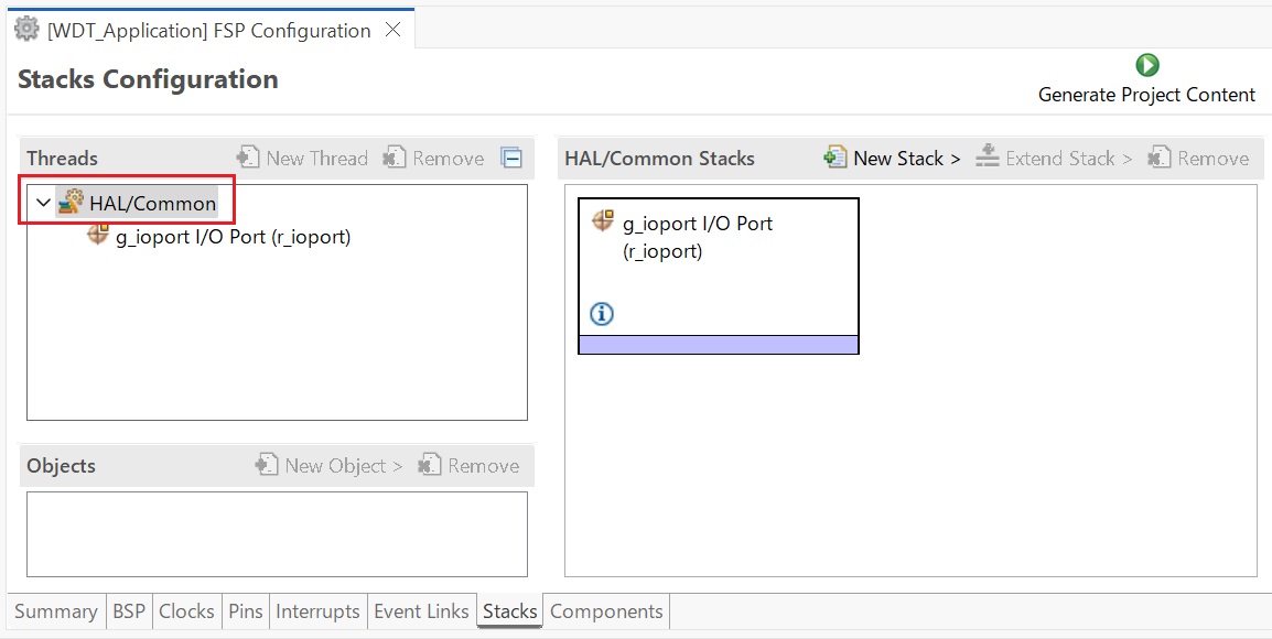
Click on the HAL/Common Panel in the Threads Window as indicated in the figure above.
The Stacks Panel becomes a HAL/Common Stacks panel and is populated with the modules preselected by e² studio.
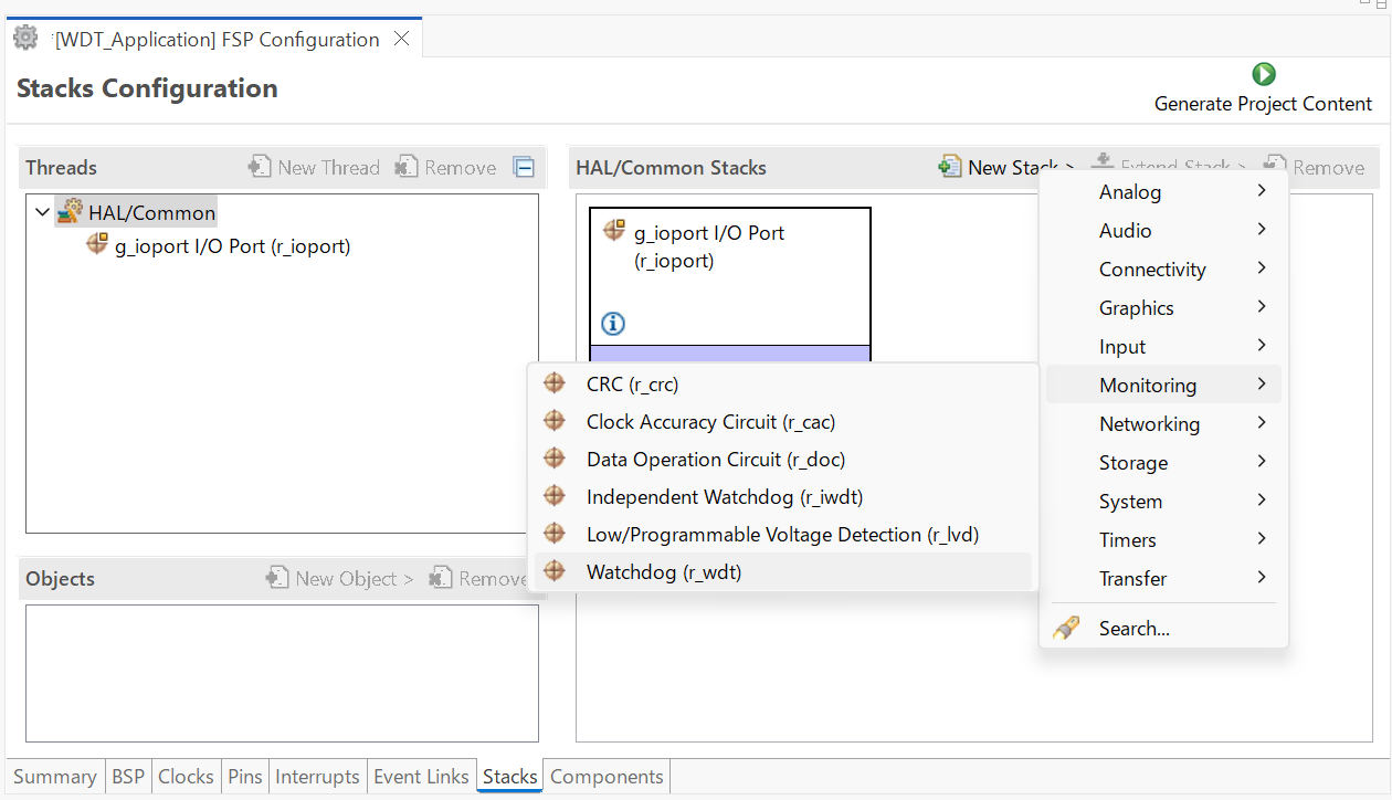
The selected HAL WDT driver is added to the HAL/Common Stacks Panel and the Property Window shows all configuration options for the selected module. The Property tab for the WDT should be visible at the bottom left of the screen. If it is not visible, check that the FSP Configuration perspective is selected.
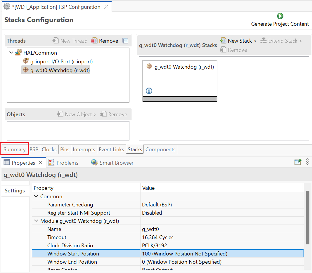
All parameters can be left with their default values.
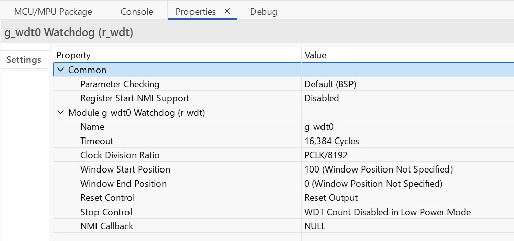
With PCLKB running at 75 MHz the WDT will reset the device 1.79 seconds after the last refresh.
WDT clock = 75 MHz / 8192 = 9.155 kHz
Cycle time = 1 / 9.155 kHz = 109.23 us
Timeout = 109.23 us x 16384 = 1.79 seconds
Save the Project Configuration file and click the Generate Project Content button in the top right corner of the Project Configuration pane.
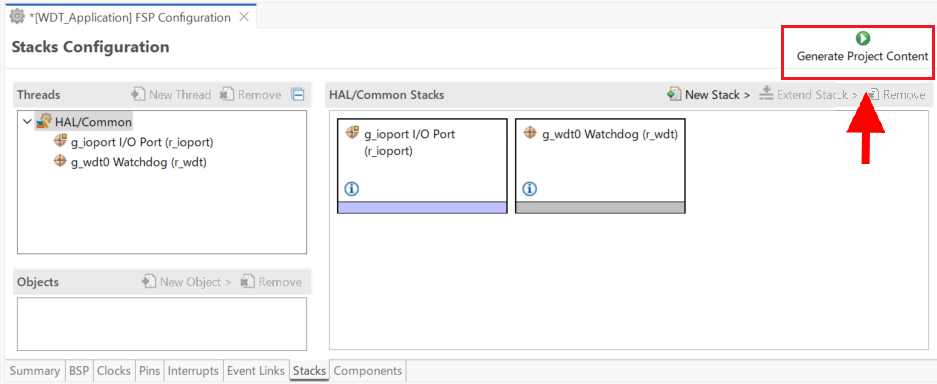
e² studio generates the project files.
The components tab is included for reference to see which modules are included in the project. Modules are selected automatically in the Components view after they are added in the Stacks Tab.
For the WDT project ensure that the following modules are selected:
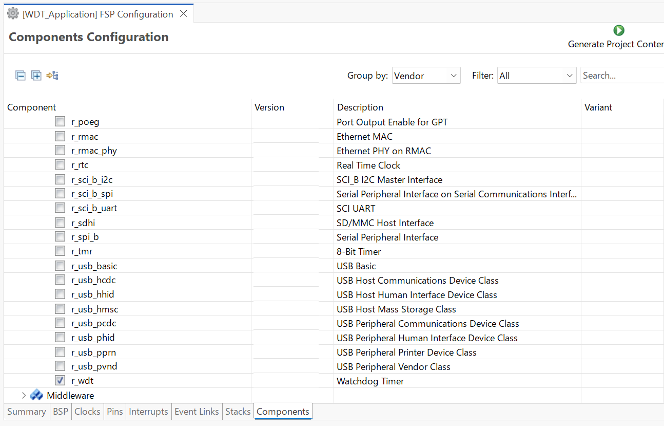
Clicking the Generate Project Content button performs the following tasks.
r_wdt folder and WDT driver contents created at:
rx/fsp/src
r_wdt_api.h created in:
rx/fsp/inc/api
r_wdt.h created in:
rx/fsp/inc/instances
The above files are the standard files for the WDT HAL module. They contain no specific project contents. They are the driver files for the WDT. Further information on the contents of these files can be found in the documentation for the WDT HAL module.
Configuration information for the WDT HAL module in the WDT project is found in:
rx_cfg/fsp_cfg/r_wdt_cfg.h
The above file's contents are based upon the Common settings in the g_wdt WATCHDOG Driver on WDT Properties pane.
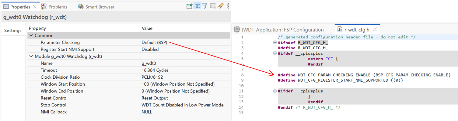
The r_ioport folder is not created at rx/fsp/src as this module is required by the BSP and so already exists. It is included in the WDT project in order to include the correct header file in rx_gen/hal_data.c–see later in this document for further details. For the same reason the other IOPORT header files– rx/fsp/inc/api/r_ioport_api.h and rx/fsp/inc/instances/r_ioport.h–are not created as they already exist.
In addition to generating the HAL driver files for the WDT and IOPORT files e² studio also generates files containing configuration data for the WDT and a file where user code can safely be added. These files are shown below.
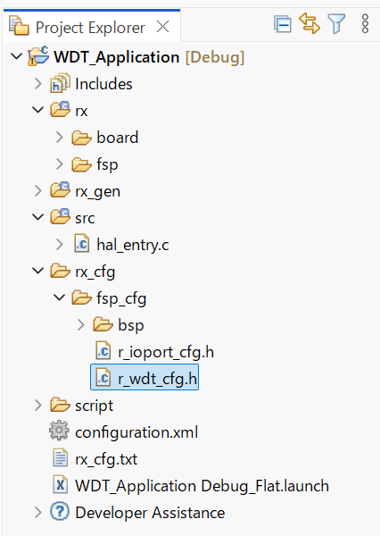
The contents of hal_data.h are shown below.
hal_data.h contains the header files required by the generated project. In addition this file includes external references to the g_wdt0 instance structure which contains pointers to the configuration, control, api structures used for WDT HAL driver.
The contents of hal_data.c are shown below.
hal_data.c contains g_wdt0_ctrl which is the control structure for this instance of the WDT HAL driver. This structure should not be initialized as this is done by the driver when it is opened.
The contents of g_wdt0_cfg are populated in this file using the Watchdog Driver on g_wdt0 pane in the Project Configuration Stacks tab. If the contents of this structure do not reflect the settings made in the IDE, ensure the Project Configuration settings are saved before clicking the Generate Project Content button.
Contains main() called by the BSP start-up code. main() calls hal_entry() which contains user developed code (see next file). Here are the contents of main.c.
This file contains the function hal_entry() called from main(). User developed code should be placed in this file and function.
For the WDT project edit the contents of this file to contain the code below. This code implements the flowchart in overview section of this document.
The WDT HAL driver API functions are defined in r_wdt.h. The WDT HAL driver is opened through the open API call using the instance structure defined in r_wdt_api.h:
The first passed parameter is the pointer to the control structure g_wdt0_ctrl instantiated in hal_data.c. The second parameter is the pointer to the configuration data g_wdto_cfg instantiated in the same hal_data.c file.
The WDT is started and refreshed through the API call:
Again the first (and only in this case) parameter passed to this API is the pointer to the control structure of this instance of the driver.
Build the project in e² studio by clicking Build > Build Project or by clicking the build icon. The project should build without errors.
To debug the project
Under Renesas GDB Hardware Debugging select WDT_Application Debug as shown below.
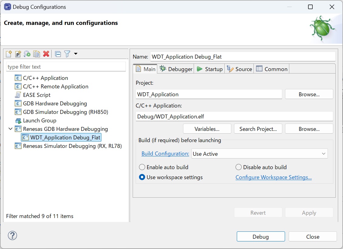
Click the Debug button. Click Yes to the debug perspective if asked.
Reset_Handler() function.main() at the call to hal_entry().The red LED should start flashing. After 30 flashes the green LED will start flashing and the red LED will stop flashing.
While the green LED is flashing the WDT will underflow and reset the device resulting in the red LED to flash again as the sequence repeats.
The Renesas RX Smart Configurator (RXSC) is a desktop application designed to configure device hardware such as clock set up and pin assignment as well as initialization of RX FSP software components for a Renesas RX microcontroller project when using a 3rd-party IDE and toolchain.
The RX Smart Configurator can currently be used with
Projects can be configured and the project content generated in the same way as in e² studio. Please refer to Configuring a Project section for more details.
IAR Systems Embedded Workbench for RX (EWRX) includes support for Renesas RX devices. These can be set up as bare metal designs within EWRX. However, most RX FSP developers will want to integrate RX FSP drivers and middleware into their designs. RXSC will facilitate this.
RXSC generates a "Project Connection" file that can be loaded directly into EWRX to update project files.
The following steps are required to create an RX FSP project using IAR EWRX, RXSC and RX FSP:
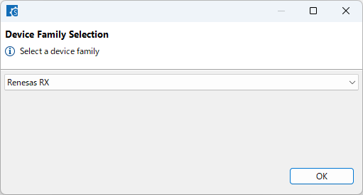
Select the target Device family.
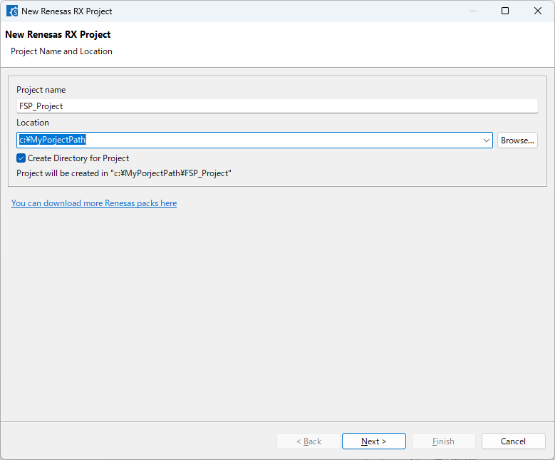
Enter a project folder and project name.
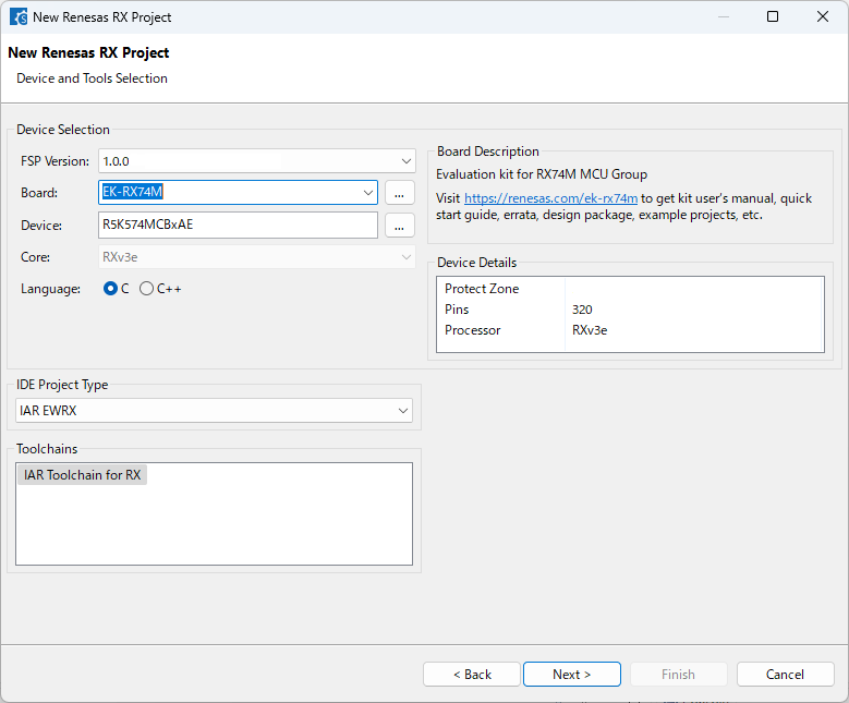
Select the target device and IDE.
rasc.exe in the installed RXSCconfiguration.xml$PROJ_DIR$buildinfo.ipcf and click Open. The project can now build in EWRX.