 |
RX Flexible Software Package Documentation
Release v1.0.0
|
|
|
RX Flexible Software Package Documentation
Release v1.0.0
|
|
Functions | |
| fsp_err_t | R_FSP_VersionGet (fsp_pack_version_t *const p_version) |
| void | Reset_Handler (void) |
| void | Default_Handler (void) |
| BSP_WEAK_REFERENCE void | R_BSP_WarmStart (bsp_warm_start_event_t event) __attribute__((noinline)) |
| void | SystemInit (void) |
| void | R_BSP_CacheEnable (void) |
| Enable caches. More... | |
| void | R_BSP_CacheDisable (void) |
| Disable caches. More... | |
| void | R_BSP_CacheClean (void) |
| Clean caches. More... | |
| void | R_BSP_CacheInvalidate (void) |
| Flush caches. More... | |
| void | R_BSP_CacheCleanInvalidate (void) |
| Clean and flush caches. More... | |
| __STATIC_INLINE void | bsp_cache_operate_all (uint8_t operate) |
| __STATIC_INLINE void | R_BSP_CacheEnableData (void) |
| __STATIC_INLINE void | R_BSP_CacheDisableData (void) |
| __STATIC_INLINE void | R_BSP_CacheCleanAllData (void) |
| __STATIC_INLINE void | R_BSP_CacheInvalidateAllData (void) |
| __STATIC_INLINE void | R_BSP_CacheCleanInvalidateAllData (void) |
| uint32_t | R_BSP_SourceClockHzGet (fsp_priv_source_clock_t clock) |
| __STATIC_INLINE IRQn_Type | R_FSP_CurrentIrqGet (void) |
| __STATIC_INLINE uint32_t | R_FSP_SystemClockHzGet (fsp_priv_clock_t clock) |
| __STATIC_INLINE uint32_t | R_FSP_ClockDividerGet (uint32_t ckdivcr) |
| __STATIC_INLINE bsp_unique_id_t const * | R_BSP_UniqueIdGet (void) |
| __STATIC_INLINE fsp_err_t | R_BSP_PartNumberGet (bsp_part_number_t *const p_part_number) |
| void | R_BSP_SoftwareDelay (uint32_t delay, bsp_delay_units_t units) |
| fsp_err_t | R_BSP_GroupIrqWrite (bsp_grp_irq_nmi_t irq, void(*p_callback)(bsp_grp_irq_nmi_t irq)) |
| void | bsp_nmi_handler (void) |
| bool | R_BSP_GroupIrqCheck (uint8_t irq) |
| uint32_t | R_BSP_GetCurrentIFlagState (void) |
| Provides the current I flag state on PSW register. More... | |
| void | R_BSP_SetIFlagState (uint32_t interrupt_mask) |
| Set I flag state on PSW register. If this flag is 0, all interrupts are disabled. More... | |
| uint32_t | R_BSP_GetCurrentIpl (void) |
| Get current interrupt priority level from PSW register. More... | |
| void | R_BSP_SetIpl (uint32_t interrupt_mask_level) |
| Set IPL state on PSW register. If the passed interrupt priority level (IPL) is maximum, all interrupts are disabled. If the passed IPL is less than the maximum, interrupts which IPL is above the set value will be processed. More... | |
| uint32_t | R_BSP_IrqIsEnabled (IRQn_Type const irq) |
| void | R_BSP_IrqStatusClear (IRQn_Type irq) |
| void | R_BSP_IrqClearPending (IRQn_Type irq) |
| void | R_BSP_IrqCfg (IRQn_Type const irq, uint32_t priority, void *p_context) |
| void | R_BSP_IrqEnableNoClear (IRQn_Type const irq) |
| void | R_BSP_IrqEnable (IRQn_Type const irq) |
| void | R_BSP_IrqDisable (IRQn_Type const irq) |
| void | R_BSP_IrqCfgEnable (IRQn_Type const irq, uint32_t priority, void *p_context) |
| void | R_BSP_RegisterProtectEnable (bsp_reg_protect_t regs_to_protect) |
| void | R_BSP_RegisterProtectDisable (bsp_reg_protect_t regs_to_unprotect) |
The BSP is responsible for getting the MCU from reset to the user's application. Before reaching the user's application, the BSP sets up the stacks, heap, clocks, interrupts, C runtime environment, and stack monitor.
All system clocks are set up during BSP initialization based on the settings in bsp_clock_cfg.h. These settings are derived from clock configuration information provided from the FSP Configuration editor Clocks tab.
As RX MCUs are based on the RXv3 architecture, the Interrupt Controller Unit (ICU) handles exceptions and interrupt configuration, prioritization and interrupt masking using the interrupt vector table (INTB) in CPU. In the exception vector table, the individual vectors are allocated to in a 124-byte area where the value indicated by the exception table register (EXTB) is used as the starting address (ExtBase). The reset vector is always allocated to FFFFFFFCh, regardless of the value of the exception vector table. The exceptions except nomal non-maskable interrupt are shown below:
Group interrupt is the term used to describe the 13 sources that can trigger the Non-Maskable Interrupt (NMI). When an NMI occurs the NMI Handler examines the NMISR (status register) to determine the source of the interrupt. NMI interrupts take precedence over all interrupts, are usable only as CPU interrupts, and cannot activate the RX peripherals Data Transfer Controller (DTC) or Direct Memory Access Controller (DMAC).
Possible group interrupt sources include:
A user may enable notification for one or NMI interrupts by registering a callback using the BSP API function R_BSP_GroupIrqWrite(). When an NMI interrupt occurs, the NMI handler checks to see if there is a callback registered for the cause of the interrupt and if so calls the registered callback function.
Maskable interrupts are Peripheral interrupts, Software interrupts, Group interrupts, External pin interrupts. User unconfigurable interrupts (software interrupts, group interrupts, external interrupts, peripheral-generated interrupts) are assigned to vector numbers 0 to 127, and user configurable interrupts (software configurable interrupts) are assigned to vector numbers 128 to 255.
By allowing the user to select only the software configurable interrupts they are interested in as interrupt sources, we are able to provide an interrupt service routine that is fast and software configurable interrupt specific.
For example, on other microcontrollers an interrupt vector table might contain a single vector entry for the SCI0 (Serial Communications Interface) peripheral. The interrupt service routine for this would have to check a status register for the 'real' source of the interrupt. In the RX implementation there is a vector entry for each of the SCI0 events that we are interested in.
Nested interrupts are explicitly enabled by setting the PSW.I bit when entering a maskable interrupt handler.
Note: RX MCUs disable nested interrupts by default. RX FSP enables nested interrupts in software.`
You might wonder how the BSP is able to place ISR addresses in the interrupt table without the user having explicitly defined one. All that is required by the BSP is that the interrupt event be given a priority.
This is accomplished through the use of the 'weak' attribute. The weak attribute causes the declaration to be emitted as a weak symbol rather than a global. A weak symbol is one that can be overridden by an accompanying strong reference with the same name. When the BSP declares a function as weak, user code can define the same function and it will be used in place of the BSP function. By defining all possible interrupt sources as weak, the vector table can be built at compile time and any user declarations (strong references) will be used at runtime.
Weak symbols are supported for ELF targets and also for a.out targets when using the GNU assembler and linker.
Note that in CMSIS system.c, there is also a weak definition (and a function body) for the Warm Start callback function R_BSP_WarmStart(). Because this function is defined in the same file as the weak declaration, it will be called as the 'default' implementation. The function may be overridden by the user by copying the body into their user application and modifying it as necessary. The linker identifies this as the 'strong' reference and uses it.
As the BSP is in the process of bringing up the board out of reset, there are three points where the user can request a callback. These are defined as the 'Pre Clock Init', 'Post Clock Init' and 'Post C' warm start callbacks.
As described above, this function is already weakly defined as R_BSP_WarmStart(), so it is a simple matter of redefining the function or copying the existing body from CMSIS system.c into the application code to get a callback. R_BSP_WarmStart() takes an event parameter of type bsp_warm_start_event_t which describes the type of warm start callback being made.
This function is not enabled/disabled and is always called for both events as part of the BSP startup. Therefore it needs a function body, which will not be called if the user is overriding it. The function body is located in system.c. To use this function just copy this function into your own code and modify it to meet your needs.
When Sub-Clock oscillator is populated in the application, the BSP startup code waits for some time(sub-clock stabilization time) to allow Sub-clock to stabilize. Enabling the watchdog (IWDT or WDT) timer with Auto start mode in an application using Sub-clock may cause system to generate Reset or NMI interrupt before reaching the application code if watchdog refresh register is not updated in the configured refresh Window. To overcome this problem a weakly defined callback R_BSP_SubClockStabilizeWait() can be overridden. Redefine the callback function in the application code and add code to update the watchdog refresh register. R_BSP_SubClockStabilizeWait() takes a parameter delay of type uint32_t which describes the time in milliseconds required to stabilize the sub-clock.
After Power-On-Reset, the BSP startup code may have to wait for some time(sub-clock stabilization time) to allow Sub-clock to stabilize. This can cause problem to RTC in case device is to be reset frequently. If Sub-Clock registers are not initialized during a reset, BSP actually does not have to wait for Sub-clock to stabilize. To overcome this problem, a weakly defined callback R_BSP_SubClockStabilizeWaitAfterReset() is provided. Reimplement the callback function in the application code to determine whether BSP has to wait for stabilization time based on the current reset type. R_BSP_SubClockStabilizeWaitAfterReset() takes a parameter delay of type uint32_t which describes the time in milliseconds required to stabilize the sub-clock.
The BSP provides support for usage of external SDRAM modules on MCUs with SDRAM support. SDRAM is enabled and configured in the BSP tab of the FSP configuration editor. The default location for initialization is in the 'Post C' warm start callback. If required, the call to R_BSP_SdramInit() can be moved anywhere after clock and pin initialization, but it must only be called once after reset.
Before entering Software Standby or Deep Software Standby, the user must call R_BSP_SdramSelfRefreshEnable() to change from Auto-Refresh to Self-Refresh in order to preserve data during the low power state. No SDRAM access is allowed after this function is called. The user must not place FSP code or data or their wakeup interrupt handling functions into SDRAM to ensure there are no issues around transitions into and out of Software Standby since SDRAM access will be disabled then and trigger a fault if access is requested.
When resuming from Software Standby, the user must call R_BSP_SdramSelfRefreshDisable() to change from Self-Refresh to Auto-Refresh and restore SDRAM access.
When resuming operation after Deep Software Standby or another situation where there is already data present in the SDRAM modules that must be preserved, the user must call R_BSP_SdramInit(false) before pin initialization and then call R_BSP_SdramSelfRefreshDisable() after pins have been configured in order to resume operations with the SDRAM.
This BSP configuration allows the user to skip the FSP C runtime initialization code by setting the "C Runtime Initialization" to "Disabled" on the BSP tab of the FSP Configuration editor. Disabling this option is useful in cases where a non-standard linker script is being used or other modifications to the runtime initialization are desired. If this macro is disabled, the user must use the 'Post Clock Init' event from the warm start (described above) to run their own runtime initialization code.
The relatively low amount of on-chip SRAM available and lack of memory protection in an MCU means that heap use must be very carefully controlled to avoid memory leaks, overruns and attempted overallocation. Further, many RTOSes provide their own dynamic memory allocation system. For these reasons the default heap size is set at 0 bytes, effectively disabling dynamic memory. If it is required for an application setting a positive value to the "Heap size (bytes)" option in the RX Common configurations on the BSP tab will allocate a heap.
When error logging is enabled, the error logging function can be redefined on the command line by defining FSP_ERROR_LOG(err) to the desired function call. The default function implementation is FSP_ERROR_LOG(err)=fsp_error_log(err, FILE, LINE). This implementation uses the predefined macros FILE and LINE to help identify the location where the error occurred. Removing the line from the function call can reduce code size when error logging is enabled. Some compilers may support other predefined macros like FUNCTION, which could be helpful for customizing the error logger.
The BSP register protection functions utilize reference counters to ensure that an application which has specified a certain register and subsequently calls another function doesn't have its register protection settings inadvertently modified.
Each time R_BSP_RegisterProtectDisable() is called, the respective reference counter is incremented.
Each time R_BSP_RegisterProtectEnable() is called, the respective reference counter is decremented.
Both functions will only modify the protection state if their reference counter is zero.
Option-setting memory includes OFS registers (e.g. OFS1), block protections settings (BPS/PBPS), and other device-dependent non-volatile options. Option-setting memory is MCU specific, and not all MCUs implement all option-setting registers. Option-setting configurations available on the selected device are configurable in the BSP properties. These configurations are placed in sections to be loaded at the required flash address by the linker.
OFS registers can be individually enabled or disabled. When an OFS register is disabled, its flash address will not be erased or programmed. The existing settings on the device will not be changed. For safety purpose, OFS registers that could limit or disable debug or ROM write access (like BANKSEL, BPS, PBPS etc.) are disabled by default. Please note:
All *_SEL registers default to allowing both Secure and Non-Secure access unless otherwise noted here. If block protection is configured in a Secure project, the BSP sets the corresponding configuration to Secure access only by updating the corresponding *_SEL register. Similarly, the PVD related settings in the OFSn_SEL registers are automatically set to Secure if the corresponding PVD monitor is used in the Secure project.
Implements a blocking software delay. A delay can be specified in microseconds, milliseconds or seconds. The delay is implemented based on the system clock rate.
To utilize the TFU hardware for trigonometric math functions, please use the functions provided by each compiler. The CCRX, GCC, and IAR compilers offer options related to TFU. These compilers provide an option to replace calls to the following mathematical library functions with TFU-enabled code. By modifying the compiler options, the trigonometric library functions sinf(), cosf(), atan2f(), hypotf() and more can be mapped to their respective TFU functions. Extended functions sincosf() and atan2hypotf() are also available when the compiler option is enabled in project settings.
Implements a critical section. Some MCUs (MCUs with the BASEPRI register) support allowing high priority interrupts to execute during critical sections. On these MCUs, interrupts with priority less than or equal to BSP_CFG_IRQ_MASK_LEVEL_FOR_CRITICAL_SECTION are not serviced in critical sections. Interrupts with higher priority than BSP_CFG_IRQ_MASK_LEVEL_FOR_CRITICAL_SECTION still execute in critical sections.
Supports changing the XSPI Clock (XSPICLK) during runtime if supported by the MCU. The XSPICLK source and clock divisor can be updated. It is user's responsibility to ensure the selected clock source is running before attempting to update XSPICLK.
The BSP supports both big-endian and little-endian. Users can configure the MCU endian through the compiler settings.
By default, FSP disables I/O port low voltage mode for devices with the LVOCR register. Presently, RX74M and RX74N devices configure I/O ports based on VCC and VCC2 voltage levels. For cases where VCC and/or VCC2 will be less than 2.7 V for these devices, the I/O port low voltage mode should be enabled for VCC.
For MCUs with D-Cache and I-Cache, limited support is available for enabling the caches and automatically configuring predefined non-cacheable and cacheable regions via the MPU during BSP initialization.
For these MCUs, D-Cache is disabled by default because certain existing drivers do not support data coherency with D-Cache enabled. Enabling the D-Cache requires that data coherency be considered in any circumstance where a core interacts with other bus members.
For these MCUs, I-Cache is also disabled by default to maintain compatibility with existing applications. Users can enable I-Cache separately if the performance benefits are desired and the application has been validated accordingly.
The predefined cacheable regions configured by the MPU when D-Cache is enabled can be used to contain data that should be cached. To use the predefined cacheable regions, place the data into the corresponding cacheable section defined by the linker script for the chosen toolchain.
Below is an example of placing buffers in cacheable regions:
uint8_t cached_uninitialized_buffer_sram[1024] BSP_PLACE_IN_SECTION(".ram_noinit");
.ram_noinit and .sdram_noinit sections were treated as uninitialized sections.The predefined non-cacheable regions configured by the MPU when D-Cache is enabled can be used to contain data that should not be cached, ensuring data coherency for that data. To use the predefined non-cacheable regions, place the data into the corresponding non-cacheable section defined by the linker script for the chosen toolchain. The predefined non-cacheable regions are not initialized by the BSP.
Below is an example of placing buffers in non-cacheable regions:
uint8_t uncached_uninitialized_buffer_sram[1024] BSP_PLACE_IN_SECTION(".ram_noinit_nocache");
.ram_noinit_nocache and .sdram_noinit_nocache sections were treated as uninitialized sections.The BSP is heavily data driven with most features and functionality being configured based on the content from configuration files. Configuration files represent the settings specified by the user and are generated when the project is built and/or when the Generate Project Content button is clicked in the FSP Configuration editor.
| Configuration | Options | Default | Description |
|---|---|---|---|
| Main stack size (bytes) | Value must be an integer multiple of 8 and between 8 and 0xFFFFFFFF | 0x400 | Set the size of the main program stack. NOTE: This entry is for the main stack. When using an RTOS, thread stacks can be configured in the properties for each thread. |
| Heap size (bytes) | Value must be 0 or an integer multiple of 8 between 8 and 0xFFFFFFFF. | 0 | The main heap is disabled by default. Set the heap size to a positive integer divisible by 8 to enable it. A minimum of 4K (0x1000) is recommended if standard library functions are to be used. |
| Protect zone root stack size (bytes) | Value must be 0 or an integer multiple of 8 between 8 and 0xFFFFFFFF. | 0x800 | The number of root interrupt stacks used by the ProtectZone hypervisor. |
| MCU Vcc (mV) | Value must between 0 and 5500 (5.5V) | 3300 | Some peripherals require different settings based on the supplied voltage. Entering Vcc here (in mV) allows the relevant driver modules to configure the associated peripherals accordingly. |
| Parameter checking |
| Disabled | When enabled, parameter checking for the BSP is turned on. In addition, any modules whose parameter checking configuration is set to 'Default (BSP)' will perform parameter checking as well. |
| Assert Failures |
| Return FSP_ERR_ASSERTION | Define the behavior of the FSP_ASSERT() macro. |
| Clock Registers not Reset Values during Startup |
| Disabled | If enabled, registers are assumed to be set to their reset value during startup. Enable this if another application such as a bootloader or Secure project has already configured the clocks before the startup code runs. |
| Main Oscillator Populated |
| Populated | Select whether or not there is a main oscillator (XTAL) on the board. This setting can be overridden in board_cfg.h. |
| PFS Protect |
| Enabled | Keep the PFS registers locked when they are not being modified. If disabled they will be unlocked during startup. |
| C Runtime Initialization |
| Enabled | Select if the C runtime initialization in the BSP is to be used. If disabled, use the BSP_WARM_START_POST_CLOCK event to run user defined equivalent. |
| Early BSP Initialization |
| Disabled | Enable this option to use BSP functions before C runtime initialization (BSP_WARM_START_RESET or BSP_WARM_START_POST_CLOCK). |
| Main Oscillator Clock Source |
| Crystal or Resonator | Select the main oscillator clock source. This setting can be overridden in board_cfg.h |
| Subclock Populated |
| Populated | Select whether or not there is a subclock crystal on the board. This setting can be overridden in board_cfg.h. |
| Subclock Drive (Drive capacitance availability varies by MCU) |
| Standard/Normal mode | Select the subclock oscillator drive capacitance. This setting can be overridden in board_cfg.h |
| Subclock Stabilization Time (ms) | Value must between 0 and 10000 | 1000 | Select the subclock oscillator stabilization time. This is only used in the startup code if the subclock is selected as the system clock on the Clocks tab or if the HOCO FLL function is enabled. This setting can be overridden in board_cfg.h |
The BSP will not initialize any memory sections in the SDRAM. The user is responsible for initializing any code or data stored in SDRAM.
FSP C++ projects are not supported with the CC-RX compiler because it does not support the C++ 11 features, which is required for C++ project. Use a C project when building with CC-RX.
Secure Service Call (SSC) to retrieve clock information from the Non-Secure world. Users can add their corresponding processing as required.
Non-Secure interrupts that occur during Secure execution are pended.
This BSP does not support hypervisor calls that invoke Non-Secure functions from the Secure world.
In ProtectZone Secure projects, Secure interrupt priorities must be higher than 15 to prevent Non-Secure interrupts from preempting Secure execution.
Secure floating-point registers are not cleared when transitioning from the Secure to the Non-Secure world.
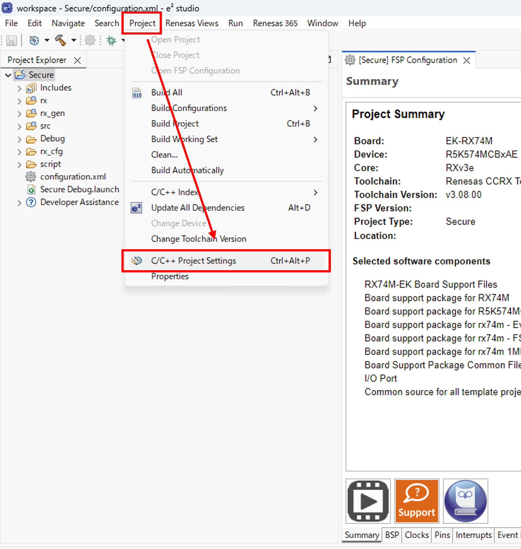
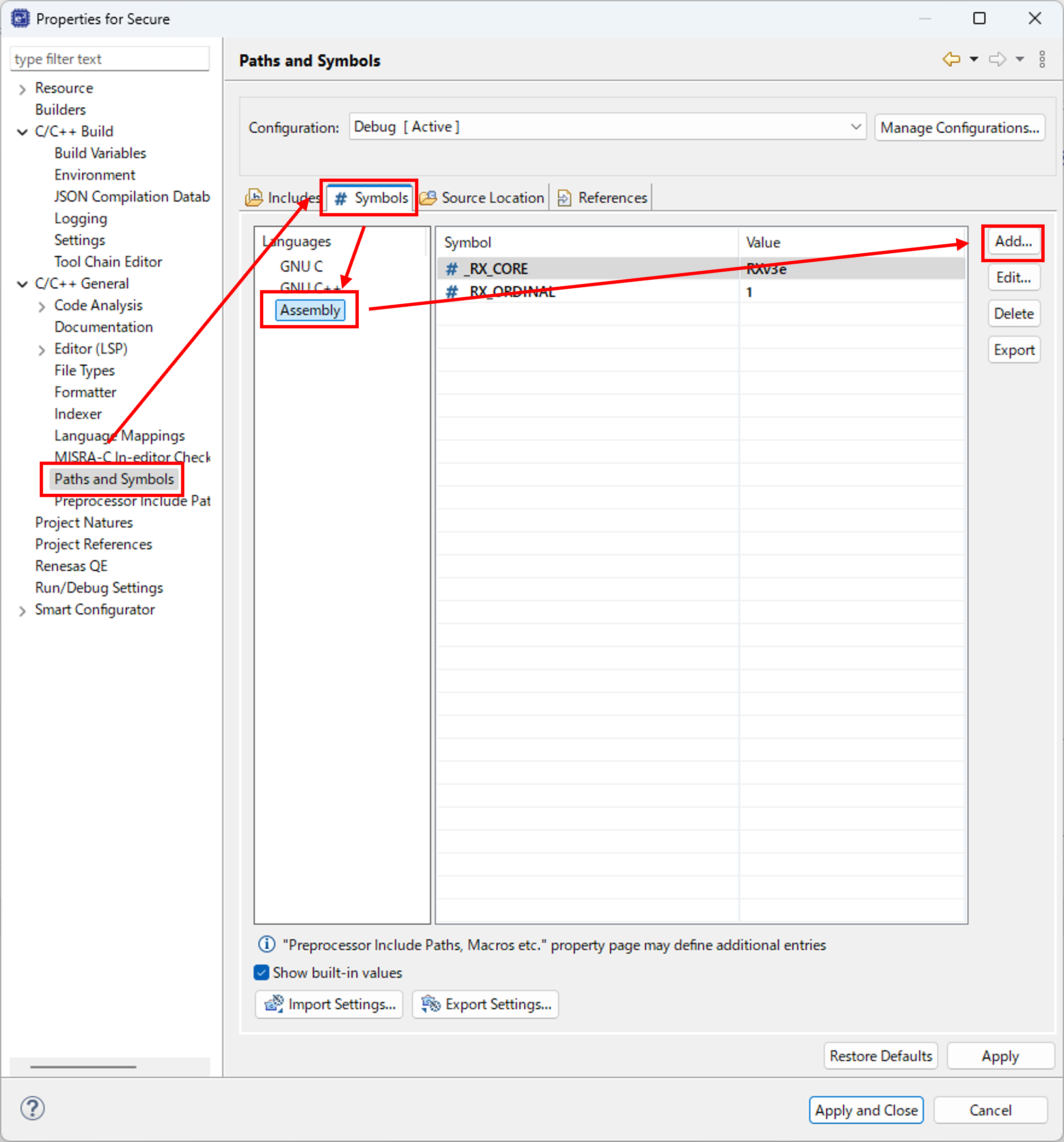
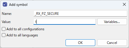
When building a secure application with the CC-RX compiler, define the _RX_PZ_SECURE assembler symbol as follows:
Modules | |
| RX74M | |
| RX74N | |
Data Structures | |
| struct | transfer_info_t |
Macros | |
| #define | BSP_IRQ_DISABLED |
| #define | FSP_LOG_PRINT(X) |
| #define | FSP_RETURN(err) |
| #define | FSP_ERROR_LOG(err) |
| #define | FSP_ASSERT(a) |
| #define | FSP_ERROR_RETURN(a, err) |
| #define | FSP_CRITICAL_SECTION_ENTER |
| #define | FSP_CRITICAL_SECTION_EXIT |
| #define | FSP_INVALID_VECTOR |
| #define | BSP_CFG_HANDLE_UNRECOVERABLE_ERROR(x) |
| #define | BSP_STACK_ALIGNMENT |
| #define | R_BSP_MODULE_START(ip, channel) |
| #define | R_BSP_MODULE_STOP(ip, channel) |
Enumerations | |
| enum | fsp_ip_t |
| enum | fsp_signal_t |
| enum | bsp_warm_start_event_t |
| enum | fsp_priv_clock_t |
| enum | fsp_priv_source_clock_t |
| enum | bsp_delay_units_t |
| enum | bsp_grp_irq_nmi_t |
| enum | bsp_reg_protect_t |
| enum | transfer_mode_t |
| enum | transfer_size_t |
| enum | transfer_addr_mode_t |
| enum | transfer_repeat_area_t |
| enum | transfer_chain_mode_t |
| enum | transfer_irq_t |
Variables | |
| uint32_t SystemCoreClock | BSP_SECTION_EARLY_INIT |
| struct transfer_info_t |
This structure specifies the properties of the transfer.
| Data Fields | ||
|---|---|---|
| union transfer_info_t | transfer_settings_u | |
| void const *volatile | p_src | Source pointer. |
| void *volatile | p_dest | Destination pointer. |
| volatile uint16_t | num_blocks |
Number of blocks to transfer when using TRANSFER_MODE_BLOCK (DTC, DMAC and EXDMAC) or TRANSFER_MODE_REPEAT (DMAC and EXDMAC only) or TRANSFER_MODE_REPEAT_BLOCK (DMAC and EXDMAC only), unused in other modes. Number of blocks to transfer when using TRANSFER_MODE_BLOCK (DTC, DMAC or EXDMAC) or TRANSFER_MODE_REPEAT (DMAC and EXDMAC only) or TRANSFER_MODE_REPEAT_BLOCK (DMAC and EXDMAC only), unused in other modes. |
| volatile uint16_t | length |
Length of each transfer. Range limited for TRANSFER_MODE_BLOCK, TRANSFER_MODE_REPEAT, and TRANSFER_MODE_REPEAT_BLOCK see HAL driver for details. |
| union transfer_info_t | transfer_settings_u | |
| #define BSP_IRQ_DISABLED |
Used to configure the interrupt priority level into level 0 for disabling the interrupt.
| #define FSP_LOG_PRINT | ( | X | ) |
Macro that can be defined in order to enable logging in FSP modules.
| #define FSP_RETURN | ( | err | ) |
Macro to log and return error without an assertion.
| #define FSP_ERROR_LOG | ( | err | ) |
This function is called before returning an error code. To stop on a runtime error, define fsp_error_log in user code and do required debugging (breakpoints, stack dump, etc) in this function.
| #define FSP_ASSERT | ( | a | ) |
Default assertion calls FSP_ERROR_RETURN if condition "a" is false. Used to identify incorrect use of API's in FSP functions.
| #define FSP_ERROR_RETURN | ( | a, | |
| err | |||
| ) |
All FSP error codes are returned using this macro. Calls FSP_ERROR_LOG function if condition "a" is false. Used to identify runtime errors in FSP functions.
| #define FSP_CRITICAL_SECTION_ENTER |
This macro temporarily saves the current interrupt state and disables interrupts.
| #define FSP_CRITICAL_SECTION_EXIT |
This macro restores the previously saved interrupt state, reenabling interrupts.
| #define FSP_INVALID_VECTOR |
Used to signify that the requested IRQ vector is not defined in this system.
| #define BSP_CFG_HANDLE_UNRECOVERABLE_ERROR | ( | x | ) |
In the event of an unrecoverable error the BSP will by default call the __BKPT() intrinsic function which will alert the user of the error. The user can override this default behavior by defining their own BSP_CFG_HANDLE_UNRECOVERABLE_ERROR macro.
| #define BSP_STACK_ALIGNMENT |
Stacks (and heap) must be sized and aligned to an integer multiple of this number.
| #define R_BSP_MODULE_START | ( | ip, | |
| channel | |||
| ) |
Cancels the module stop state.
| ip | fsp_ip_t enum value for the module to be stopped |
| channel | The channel. Use channel 0 for modules without channels. |
| #define R_BSP_MODULE_STOP | ( | ip, | |
| channel | |||
| ) |
Enables the module stop state.
| ip | fsp_ip_t enum value for the module to be stopped |
| channel | The channel. Use channel 0 for modules without channels. |
| enum fsp_ip_t |
Available modules.
| enum fsp_signal_t |
Signals that can be mapped to an interrupt.
Different warm start entry locations in the BSP.
| enum fsp_priv_clock_t |
| enum bsp_delay_units_t |
Available delay units for R_BSP_SoftwareDelay(). These are ultimately used to calculate a total # of microseconds
| enum bsp_grp_irq_nmi_t |
Which interrupts can have callbacks registered.
| enum bsp_reg_protect_t |
The different types of registers that can be protected.
| enum transfer_mode_t |
Transfer mode describes what will happen when a transfer request occurs.
| Enumerator | |
|---|---|
| TRANSFER_MODE_NORMAL | In normal mode, each transfer request causes a transfer of transfer_size_t from the source pointer to the destination pointer. The transfer length is decremented and the source and address pointers are updated according to transfer_addr_mode_t. After the transfer length reaches 0, transfer requests will not cause any further transfers. |
| TRANSFER_MODE_REPEAT | Repeat mode is like normal mode, except that when the transfer length reaches 0, the pointer to the repeat area and the transfer length will be reset to their initial values. If DMAC or EXDMAC is used, the transfer repeats only transfer_info_t::num_blocks times. After the transfer repeats transfer_info_t::num_blocks times, transfer requests will not cause any further transfers. If DTC is used, the transfer repeats continuously (no limit to the number of repeat transfers). |
| TRANSFER_MODE_BLOCK | In block mode, each transfer request causes transfer_info_t::length transfers of transfer_size_t. After each individual transfer, the source and destination pointers are updated according to transfer_addr_mode_t. After the block transfer is complete, transfer_info_t::num_blocks is decremented. After the transfer_info_t::num_blocks reaches 0, transfer requests will not cause any further transfers. |
| TRANSFER_MODE_REPEAT_BLOCK | In addition to block mode features, repeat-block mode supports a ring buffer of blocks and offsets within a block (to split blocks into arrays of their first data, second data, etc.) |
| TRANSFER_MODE_NORMAL | In normal mode, each transfer request causes a transfer of transfer_size_t from the source pointer to the destination pointer. The transfer length is decremented and the source and address pointers are updated according to transfer_addr_mode_t. After the transfer length reaches 0, transfer requests will not cause any further transfers. |
| TRANSFER_MODE_REPEAT | Repeat mode is like normal mode, except that when the transfer length reaches 0, the pointer to the repeat area and the transfer length will be reset to their initial values. If DMAC or EXDMAC is used, the transfer repeats only transfer_info_t::num_blocks times. After the transfer repeats transfer_info_t::num_blocks times, transfer requests will not cause any further transfers. If DTC is used, the transfer repeats continuously (no limit to the number of repeat transfers). |
| TRANSFER_MODE_BLOCK | In block mode, each transfer request causes transfer_info_t::length transfers of transfer_size_t. After each individual transfer, the source and destination pointers are updated according to transfer_addr_mode_t. After the block transfer is complete, transfer_info_t::num_blocks is decremented. After the transfer_info_t::num_blocks reaches 0, transfer requests will not cause any further transfers. |
| TRANSFER_MODE_REPEAT_BLOCK | In addition to block mode features, repeat-block mode supports a ring buffer of blocks and offsets within a block (to split blocks into arrays of their first data, second data, etc.) |
| enum transfer_size_t |
Transfer size specifies the size of each individual transfer. Total transfer length = transfer_size_t * transfer_length_t
| enum transfer_addr_mode_t |
Address mode specifies whether to modify (increment or decrement) pointer after each transfer.
| Enumerator | |
|---|---|
| TRANSFER_ADDR_MODE_FIXED | Address pointer remains fixed after each transfer. |
| TRANSFER_ADDR_MODE_OFFSET | Offset is added to the address pointer after each transfer. |
| TRANSFER_ADDR_MODE_INCREMENTED | Address pointer is incremented by associated transfer_size_t after each transfer. |
| TRANSFER_ADDR_MODE_DECREMENTED | Address pointer is decremented by associated transfer_size_t after each transfer. |
| TRANSFER_ADDR_MODE_FIXED | Address pointer remains fixed after each transfer. |
| TRANSFER_ADDR_MODE_OFFSET | Offset is added to the address pointer after each transfer. |
| TRANSFER_ADDR_MODE_INCREMENTED | Address pointer is incremented by associated transfer_size_t after each transfer. |
| TRANSFER_ADDR_MODE_DECREMENTED | Address pointer is decremented by associated transfer_size_t after each transfer. |
Repeat area options (source or destination). In TRANSFER_MODE_REPEAT, the selected pointer returns to its original value after transfer_info_t::length transfers. In TRANSFER_MODE_BLOCK and TRANSFER_MODE_REPEAT_BLOCK, the selected pointer returns to its original value after each transfer.
| Enumerator | |
|---|---|
| TRANSFER_REPEAT_AREA_DESTINATION | Destination area repeated in TRANSFER_MODE_REPEAT or TRANSFER_MODE_BLOCK or TRANSFER_MODE_REPEAT_BLOCK. |
| TRANSFER_REPEAT_AREA_SOURCE | Source area repeated in TRANSFER_MODE_REPEAT or TRANSFER_MODE_BLOCK or TRANSFER_MODE_REPEAT_BLOCK. |
| TRANSFER_REPEAT_AREA_DESTINATION | Destination area repeated in TRANSFER_MODE_REPEAT or TRANSFER_MODE_BLOCK or TRANSFER_MODE_REPEAT_BLOCK. |
| TRANSFER_REPEAT_AREA_SOURCE | Source area repeated in TRANSFER_MODE_REPEAT or TRANSFER_MODE_BLOCK or TRANSFER_MODE_REPEAT_BLOCK. |
Chain transfer mode options.
| Enumerator | |
|---|---|
| TRANSFER_CHAIN_MODE_DISABLED | Chain mode not used. |
| TRANSFER_CHAIN_MODE_EACH | Switch to next transfer after a single transfer from this transfer_info_t. |
| TRANSFER_CHAIN_MODE_END | Complete the entire transfer defined in this transfer_info_t before chaining to next transfer. |
| TRANSFER_CHAIN_MODE_DISABLED | Chain mode not used. |
| TRANSFER_CHAIN_MODE_EACH | Switch to next transfer after a single transfer from this transfer_info_t. |
| TRANSFER_CHAIN_MODE_END | Complete the entire transfer defined in this transfer_info_t before chaining to next transfer. |
| enum transfer_irq_t |
Interrupt options.
| fsp_err_t R_FSP_VersionGet | ( | fsp_pack_version_t *const | p_version | ) |
Get the FSP version based on compile time macros.
| [out] | p_version | Memory address to return version information to. |
| FSP_SUCCESS | Version information stored. |
| FSP_ERR_ASSERTION | The parameter p_version is NULL. |
| void Reset_Handler | ( | void | ) |
MCU starts executing here out of reset. Main stack pointer is set up already.
| void Default_Handler | ( | void | ) |
Default exception handler.
| void R_BSP_WarmStart | ( | bsp_warm_start_event_t | event | ) |
This function is called at various points during the startup process. This function is declared as a weak symbol higher up in this file because it is meant to be overridden by a user implemented version. One of the main uses for this function is to call functional safety code during the startup process. To use this function just copy this function into your own code and modify it to meet your needs.
| [in] | event | Where the code currently is in the start up process |
| void SystemInit | ( | void | ) |
Initialize the MCU and the runtime environment.
| void R_BSP_CacheEnable | ( | void | ) |
Enable caches.
Enables all configured cache regions.
| void R_BSP_CacheDisable | ( | void | ) |
Disable caches.
Disable all configured cache regions.
| void R_BSP_CacheClean | ( | void | ) |
Clean caches.
Writes back any modified cache contents to memory.
| void R_BSP_CacheInvalidate | ( | void | ) |
Flush caches.
Invalidates all cache entries without writing back cached data to memory. Any modified cache contents that have not been cleaned may be discarded.
| void R_BSP_CacheCleanInvalidate | ( | void | ) |
Clean and flush caches.
Writes back any modified cache contents to memory and invalidates all cache entries.
| __STATIC_INLINE void bsp_cache_operate_all | ( | uint8_t | operate | ) |
Cache operation to all area.
| [in] | operate | Cache operation. BSP_PRV_DCACHE_INV(0) - Cache invalidate. BSP_PRV_DCACHE_CLEAN(1) - Cache clean. BSP_PRV_DCACHE_CLEAN_INV(2) - Cache clean and invalidate. |
| __STATIC_INLINE void R_BSP_CacheEnableData | ( | void | ) |
Enable Data cache.
| __STATIC_INLINE void R_BSP_CacheDisableData | ( | void | ) |
Disable Data cache.
| __STATIC_INLINE void R_BSP_CacheCleanAllData | ( | void | ) |
Clean whole of the data cache.
| __STATIC_INLINE void R_BSP_CacheInvalidateAllData | ( | void | ) |
Invalidate whole of the data cache.
| __STATIC_INLINE void R_BSP_CacheCleanInvalidateAllData | ( | void | ) |
Clean and invalidate the whole of data cache.
| uint32_t R_BSP_SourceClockHzGet | ( | fsp_priv_source_clock_t | clock | ) |
Gets the frequency of a source clock.
| [in] | clock | Element of clock souce enum which provides clock source. |
| __STATIC_INLINE IRQn_Type R_FSP_CurrentIrqGet | ( | void | ) |
Return active interrupt vector number value
| __STATIC_INLINE uint32_t R_FSP_SystemClockHzGet | ( | fsp_priv_clock_t | clock | ) |
Gets the frequency of a system clock.
| __STATIC_INLINE uint32_t R_FSP_ClockDividerGet | ( | uint32_t | ckdivcr | ) |
Converts a clock's CKDIVCR register value to a clock divider (Eg: SPICKDIVCR).
| __STATIC_INLINE bsp_unique_id_t const* R_BSP_UniqueIdGet | ( | void | ) |
Get unique ID for this device.
| __STATIC_INLINE fsp_err_t R_BSP_PartNumberGet | ( | bsp_part_number_t *const | p_part_number | ) |
Get part number for this device.
| [out] | p_part_number | Memory address to return MCU's part number to. |
| FSP_SUCCESS | Part number information stored. |
| FSP_ERR_ASSERTION | The parameter p_part_number is NULL. |
| FSP_ERR_NOT_FOUND | An error occurred when retrieving data from part number register. |
| void R_BSP_SoftwareDelay | ( | uint32_t | delay, |
| bsp_delay_units_t | units | ||
| ) |
Delay for at least the specified duration in units and return.
| [in] | delay | The number of 'units' to delay. |
| [in] | units | The 'base' (bsp_delay_units_t) for the units specified. Valid values are: BSP_DELAY_UNITS_SECONDS, BSP_DELAY_UNITS_MILLISECONDS, BSP_DELAY_UNITS_MICROSECONDS. For example: At 1 MHz one cycle takes 1 microsecond (.000001 seconds). At 12 MHz one cycle takes 1/12 microsecond or 83 nanoseconds. Therefore one run through bsp_prv_software_delay_loop() takes: ~ (83 * BSP_DELAY_LOOP_CYCLES) or 332 ns. A delay of 2 us therefore requires 2000ns/332ns or 6 loops. |
The 'theoretical' maximum delay that may be obtained is determined by a full 32 bit loop count and the system clock rate. @120MHz: ((0xFFFFFFFF loops * 4 cycles /loop) / 120000000) = 143 seconds. @32MHz: ((0xFFFFFFFF loops * 4 cycles /loop) / 32000000) = 536 seconds
Note that requests for very large delays will be affected by rounding in the calculations and the actual delay achieved may be slightly longer. @32 MHz, for example, a request for 532 seconds will be closer to 536 seconds.
Note also that if the calculations result in a loop_cnt of zero, the bsp_prv_software_delay_loop() function is not called at all. In this case the requested delay is too small (nanoseconds) to be carried out by the loop itself, and the overhead associated with executing the code to just get to this point has certainly satisfied the requested delay.
| fsp_err_t R_BSP_GroupIrqWrite | ( | bsp_grp_irq_nmi_t | irq, |
| void(*)(bsp_grp_irq_nmi_t irq) | p_callback | ||
| ) |
Register a callback function for supported interrupts. If NULL is passed for the callback argument then any previously registered callbacks are unregistered.
| [in] | irq | Interrupt for which to register a callback. |
| [in] | p_callback | Pointer to function to call when interrupt occurs. |
| FSP_SUCCESS | Callback registered |
| FSP_ERR_ASSERTION | Callback pointer is NULL |
| void bsp_nmi_handler | ( | void | ) |
Non-maskable interrupt handler. This exception is defined by the BSP, unlike other system exceptions, because there are many sources that map to the NMI exception.
| bool R_BSP_GroupIrqCheck | ( | uint8_t | irq | ) |
Non-maskable interrupt handler.
| uint32_t R_BSP_GetCurrentIFlagState | ( | void | ) |
Provides the current I flag state on PSW register.
| 0 | Disabled interrupts. |
| 1 | Enabled interrupts. |
| void R_BSP_SetIFlagState | ( | uint32_t | interrupt_mask | ) |
Set I flag state on PSW register. If this flag is 0, all interrupts are disabled.
| [in] | interrupt_mask | Value to set to the I-flag. |
| uint32_t R_BSP_GetCurrentIpl | ( | void | ) |
Get current interrupt priority level from PSW register.
| void R_BSP_SetIpl | ( | uint32_t | interrupt_mask_level | ) |
Set IPL state on PSW register. If the passed interrupt priority level (IPL) is maximum, all interrupts are disabled. If the passed IPL is less than the maximum, interrupts which IPL is above the set value will be processed.
| [in] | interrupt_mask_level | Interrupt priority to be masked. |
| uint32_t R_BSP_IrqIsEnabled | ( | IRQn_Type const | irq | ) |
Get interrupt request enable status.
| [in] | irq | The IRQ to get interrupt request enable. Note that the enums listed for IRQn_Type are only those for the Cortex Processor Exceptions Numbers. |
| 0 | Interrupt request is disabled. |
| 1 | Interrupt request is enabled. |
| void R_BSP_IrqStatusClear | ( | IRQn_Type | irq | ) |
Clear the interrupt status flag (IR) for a given interrupt. When an interrupt is triggered the IR bit is set. If it is not cleared in the ISR then the interrupt will trigger again immediately.
| [in] | irq | Interrupt for which to clear the IR bit. Note that the enums listed for IRQn_Type are only those for the Cortex Processor Exceptions Numbers. |
| void R_BSP_IrqClearPending | ( | IRQn_Type | irq | ) |
Clear the interrupt status flag (IR) for a given interrupt and clear the ICU pending interrupt.
| [in] | irq | Interrupt for which to clear the IR bit. Note that the enums listed for IRQn_Type are only those for the Cortex Processor Exceptions Numbers. |
| void R_BSP_IrqCfg | ( | IRQn_Type const | irq, |
| uint32_t | priority, | ||
| void * | p_context | ||
| ) |
Sets the interrupt priority and context.
| [in] | irq | The IRQ to configure. |
| [in] | priority | ICU priority of the interrupt |
| [in] | p_context | The interrupt context is a pointer to data required in the ISR. |
| void R_BSP_IrqEnableNoClear | ( | IRQn_Type const | irq | ) |
Enable the IRQ in the ICU (Without clearing the pending bit).
| [in] | irq | The IRQ to enable. Note that the enums listed for IRQn_Type are only those for the Cortex Processor Exceptions Numbers. |
| void R_BSP_IrqEnable | ( | IRQn_Type const | irq | ) |
Clears pending interrupts in the ICU, then enables the interrupt.
| [in] | irq | Interrupt for which to clear the IR bit and enable in the ICU. Note that the enums listed for IRQn_Type are only those for the Cortex Processor Exceptions Numbers. |
| void R_BSP_IrqDisable | ( | IRQn_Type const | irq | ) |
Disables interrupts in the ICU.
| [in] | irq | The IRQ to disable in the ICU. Note that the enums listed for IRQn_Type are only those for the Cortex Processor Exceptions Numbers. |
| void R_BSP_IrqCfgEnable | ( | IRQn_Type const | irq, |
| uint32_t | priority, | ||
| void * | p_context | ||
| ) |
Sets the interrupt priority and context, clears pending interrupts, then enables the interrupt.
| [in] | irq | Interrupt number. |
| [in] | priority | ICU priority of the interrupt |
| [in] | p_context | The interrupt context is a pointer to data required in the ISR. |
| void R_BSP_RegisterProtectEnable | ( | bsp_reg_protect_t | regs_to_protect | ) |
Enable register protection. Registers that are protected cannot be written to. Register protection is enabled by using the Protect Register (PRCR) and the MPC's Write-Protect Register (PWPR).
| [in] | regs_to_protect | Registers which have write protection enabled. |
| void R_BSP_RegisterProtectDisable | ( | bsp_reg_protect_t | regs_to_unprotect | ) |
Disable register protection. Registers that are protected cannot be written to. Register protection is disabled by using the Protect Register (PRCR) and the MPC's Write-Protect Register (PWPR).
| [in] | regs_to_unprotect | Registers which have write protection disabled. |
| uint32_t SystemCoreClock BSP_SECTION_EARLY_INIT |
System Clock Frequency (Core Clock)