|
RA Flexible Software Package Documentation
Release v6.5.1
|
|
|
RA Flexible Software Package Documentation
Release v6.5.1
|
|
The wealth of resources available to learn about and use e² studio and FSP can be overwhelming on first inspection, so this section provides a Starting Development Guide with a list of the most important initial steps. Following these highly recommended first 11 steps will bring you up to speed on the development environment in record time. Even experienced developers can benefit from the use of this guide, to learn the terminology that might be unfamiliar or different from previous environments.
Renesas e² studio is a development tool encompassing code development, build, and debug. e² studio is based on the open-source Eclipse IDE and the associated C/C++ Development Tooling (CDT).
When developing for RA MCUs, e² studio hosts the Renesas Flexible Software Package (FSP). FSP provides a wide range of time saving tools to simplify the selection, configuration, and management of modules and threads, to easily implement complex applications. The time saving tools available in e² studio and FSP include the following:
e² studio organizes project work based on Perspectives, Views, Windows, Panes, and Pages (sometimes called Tabs). A window is a section of the e² studio GUI that presents information on a key topic. Windows often use tabs to select sub-topics. For example, an editor window might have a tab available for each open file, so it is easy to switch back and forth between them. A window Pane is a section of a window. Within a window, multiple Panes can be opened and viewed simultaneously, as opposed to a tabbed window, where only individual content is displayed. A memory-display Window, for example, might have multiple Panes that allow the data to be displayed in different formats, simultaneously. A Perspective is a collection of Views and Windows typical for a specific stage of development. The default perspectives are a C/C++ Perspective, an FSP Configuration Perspective and a Debug Perspective. These provide specific Views, Windows, Tabs, and Panes tailored for the common tasks needed during the specific development stage.
In addition to managing project development, selecting modules, configuring them and simplifying code development, e² studio also hosts the engine for automatically generating code based on module selections and configurations. The engine continually checks for dependencies and automatically adds any needed lower level modules to the module stack. It also identifies any lower level modules that require configuration (for example, an interrupt that needs to have a priority assigned). It also provides a guide for selecting between multiple choices or options to make it easy to complete a fully functional module stack.
The Generate Project Content function takes the selected and configured modules and automatically generates the complete and correct configuration code. The code is added to the folders visible in the Project Explorer window in e² studio. The configuration.xml file in the project folder holds all the generated configuration settings. This file can be opened in the GUI-based RA Configuration editor to make further edits and changes. Once a project has been generated, you can go back and reconfigure any of the modules and settings if required using this editor.
To develop applications with FSP, start with one of the Renesas RA MCU Evaluation Kits. The Renesas RA MCU Evaluation Kits are designed to seamlessly integrate with e² studio.
Ordering information, Quick Start Guides, User Manuals, and other related documents for all RA MCU Evaluation Kits are available at https://www.renesas.com/ra.
The following are the minimum PC requirements to use e² studio:
Detailed installation instructions for e² studio and FSP are available on the Renesas website https://www.renesas.com/fsp. Review the release notes for e² studio to ensure that the e² studio version supports the selected FSP version. The starting version of the installer includes all features of the RA MCUs.
e² studio can work with several toolchains and toolchain versions such as the GNU Arm compiler, Arm AC6, and LLVM Embedded Toolchain for Arm. Versions of the GNU Arm and LLVM compilers verified for use with FSP are included in the e² studio installer.
FSP licensing includes full source code, limited to Renesas hardware only.
In e² studio, all FSP applications are organized in RA MCU projects. Setting up an RA MCU project involves:
These steps are described in detail in the next two sections. When you have existing projects already, after you launch e² studio and select a workspace, all projects previously saved in the selected workspace are loaded and displayed in the Project Explorer window. Each project has an associated configuration file named configuration.xml, which is located in the project's root directory.
Double-click on the configuration.xml file to open the RA MCU Project Editor. To edit the project configuration, make sure that the FSP Configuration perspective is selected in the upper right hand corner of the e² studio window. Once selected, you can use the editor to view or modify the configuration settings associated with this project.
configuration.xml file) is saved, a verbose RA Project Report file (ra_cfg.txt) with all the project settings is generated. The format allows differences to be easily viewed using a text comparison tool. The generated file is located in the project root directory.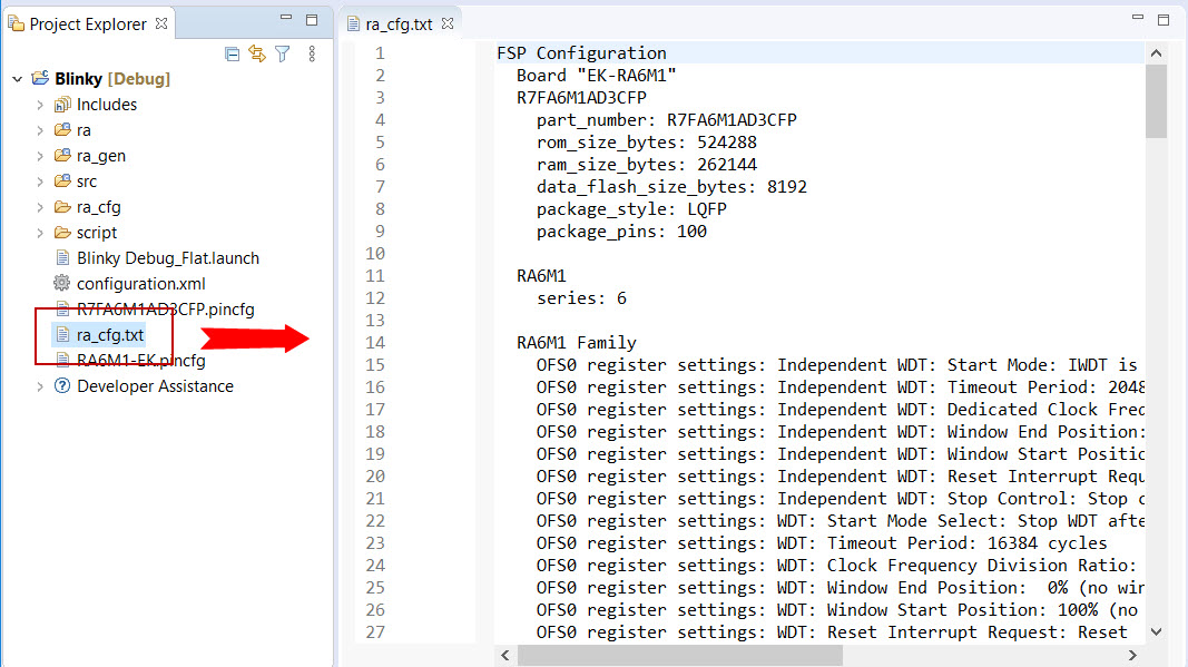
The RA Project Editor has a number of tabs. The configuration steps and options for individual tabs are discussed in the following sections.
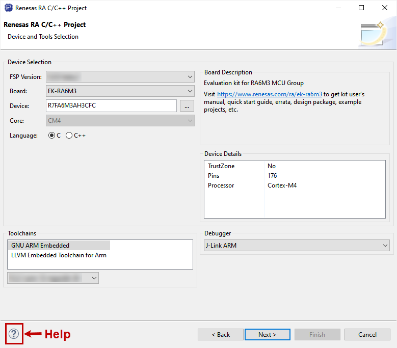
During project creation, you specify the type of project, give it a project name and location, and configure the project settings for version, target board, whether an RTOS is included, the toolchain version, and the beginning template. This section includes easy-to-follow step-by-step instructions for all of the project creation tasks. Once you have created the project, you can move to configuring the project hardware (clocks, pins, interrupts) and the parameters of all the modules that are part of your application.
For RA MCU applications, generate a new project using the following steps:
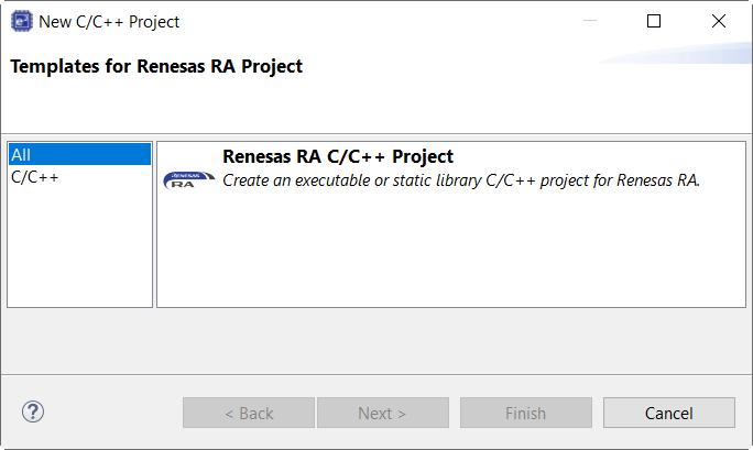
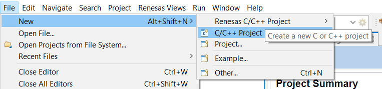
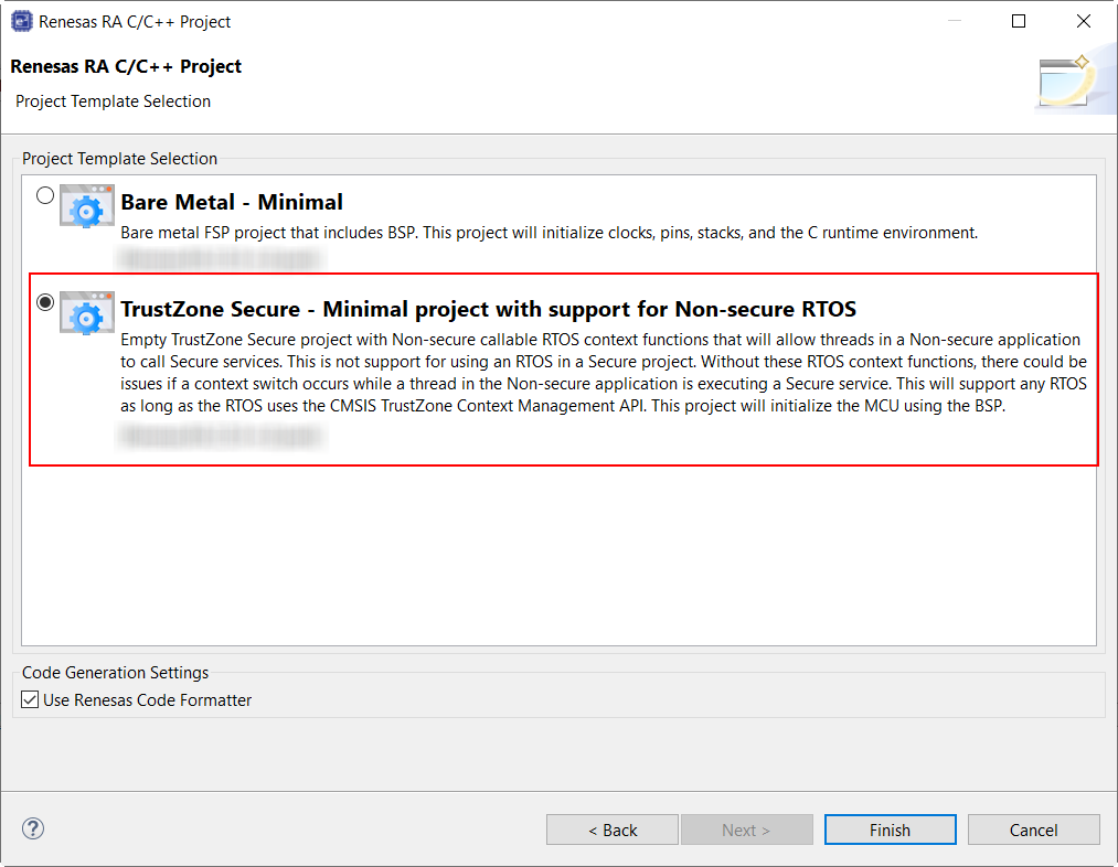
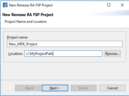
Click on File > New > RA C/C++ Project > Renesas RA.

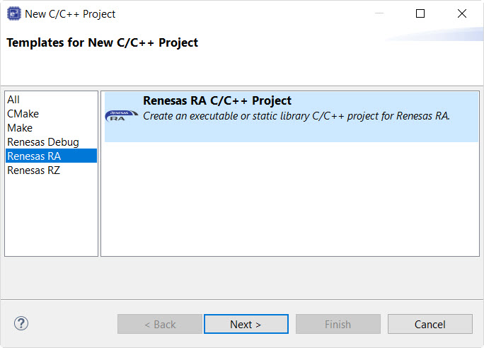
Then click on the type of template for the type of project you are creating.
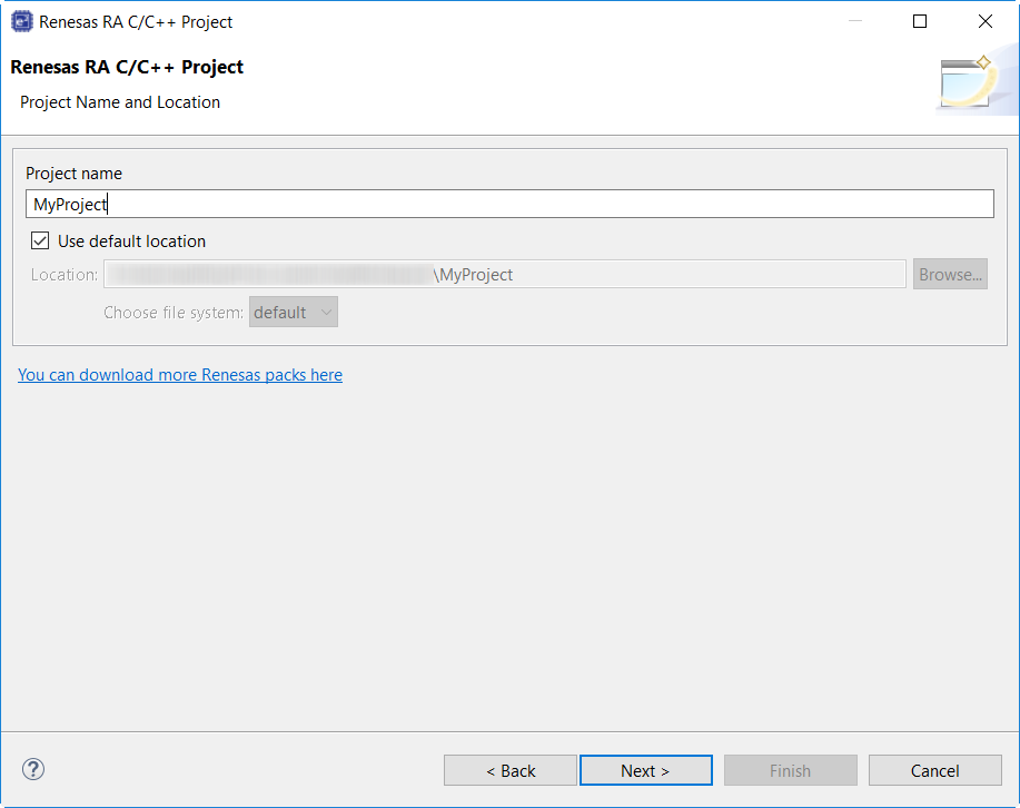
Select a project name and location.
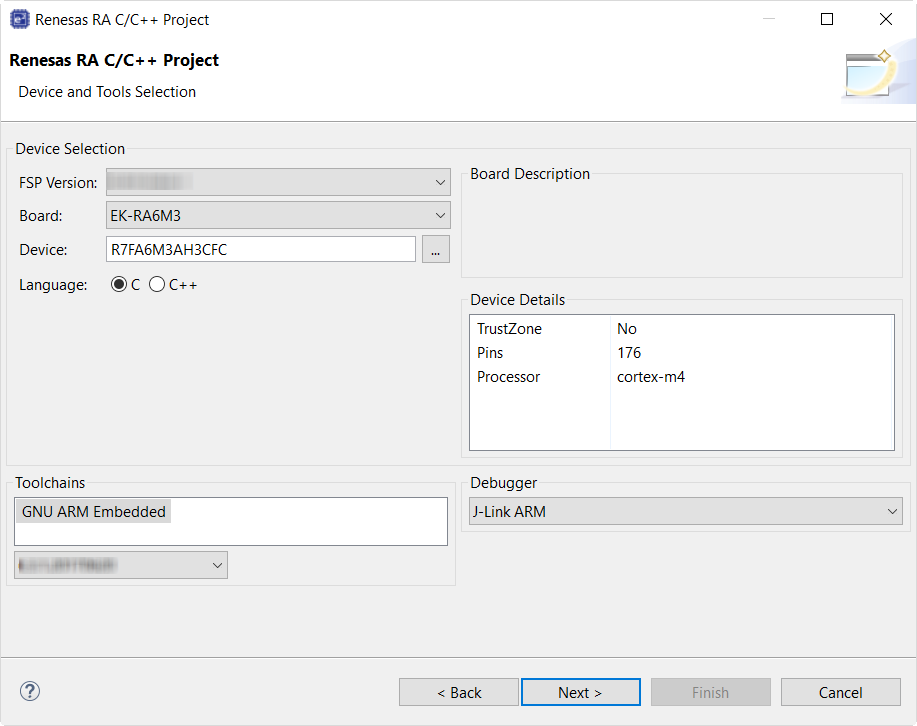
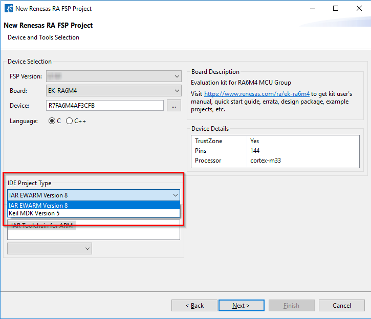
In the Project Configuration window select the hardware and software environment:
Click Next.
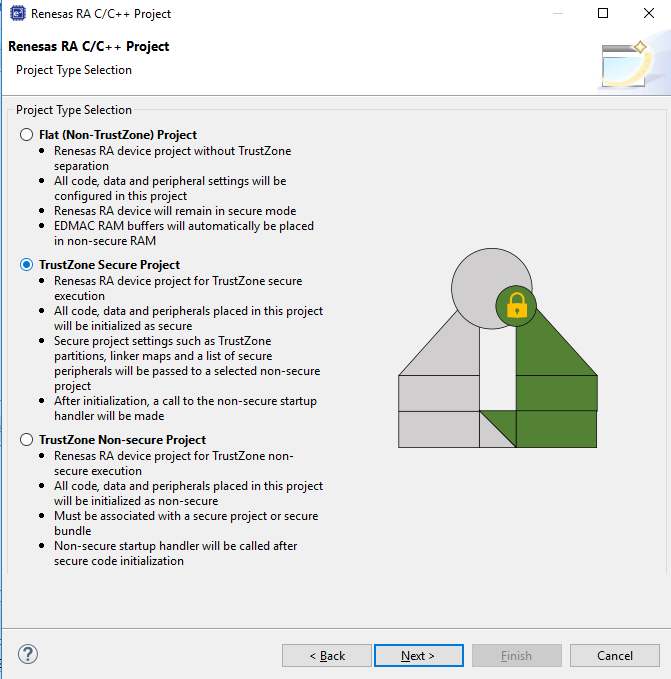
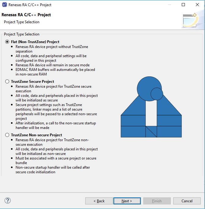
If you selected a device or tool based on an Arm® Cortex®-M33, you next select whether to use Arm® TrustZone® technology in your project. For normal, non-TrustZone projects, select "Flat".
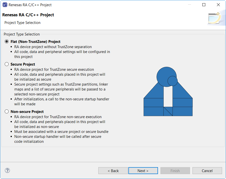
For more information on Arm TrustZone technology, see Primer: Arm TrustZone Project Development.
In the next window, select the buiild artifact and RTOS.

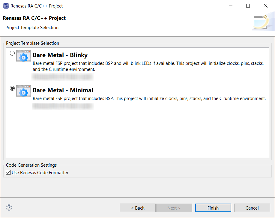
In the next window, select a project template from the list of available templates. By default, this screen shows the templates that are included in your current RA MCU pack. Once you have selected the appropriate template, click Finish.
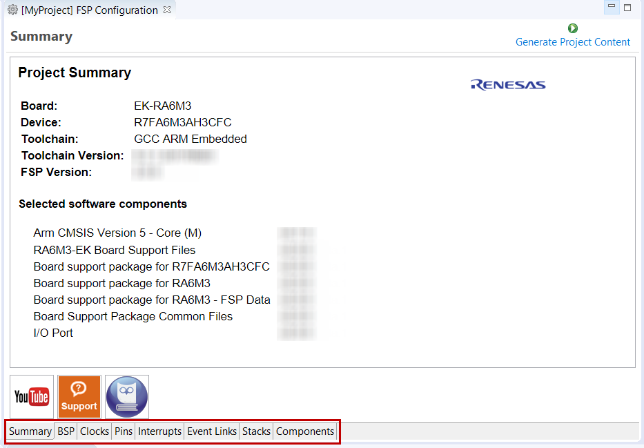
When the project is created, e² studio displays a summary of the current project configuration in the RA MCU Project Editor.
On the bottom of the RA MCU Project Editor view, you can find the tabs for configuring multiple aspects of your project:
The functions and use of each of these tabs is explained in detail in the next section.
Each of the configurable elements in an FSP project can be edited using the appropriate tab in the RA Configuration editor window. Importantly, the initial configuration of the MCU after reset and before any user code is executed is set by the configuration settings in the BSP, Clocks and Pins tabs. When you select a project template during project creation, e² studio configures default values that are appropriate for the associated board. You can change those default values as needed. The following sections detail the process of configuring each of the project elements for each of the associated tabs.
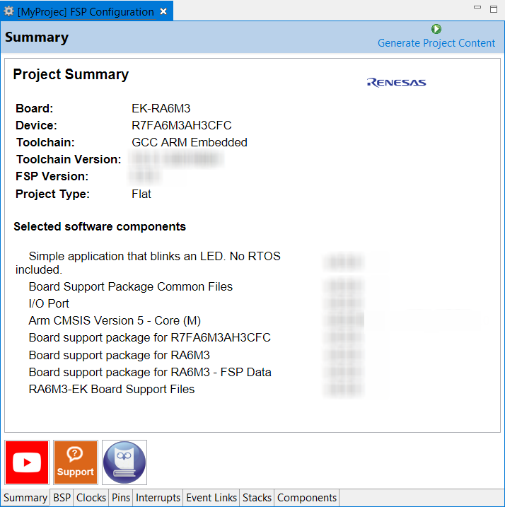
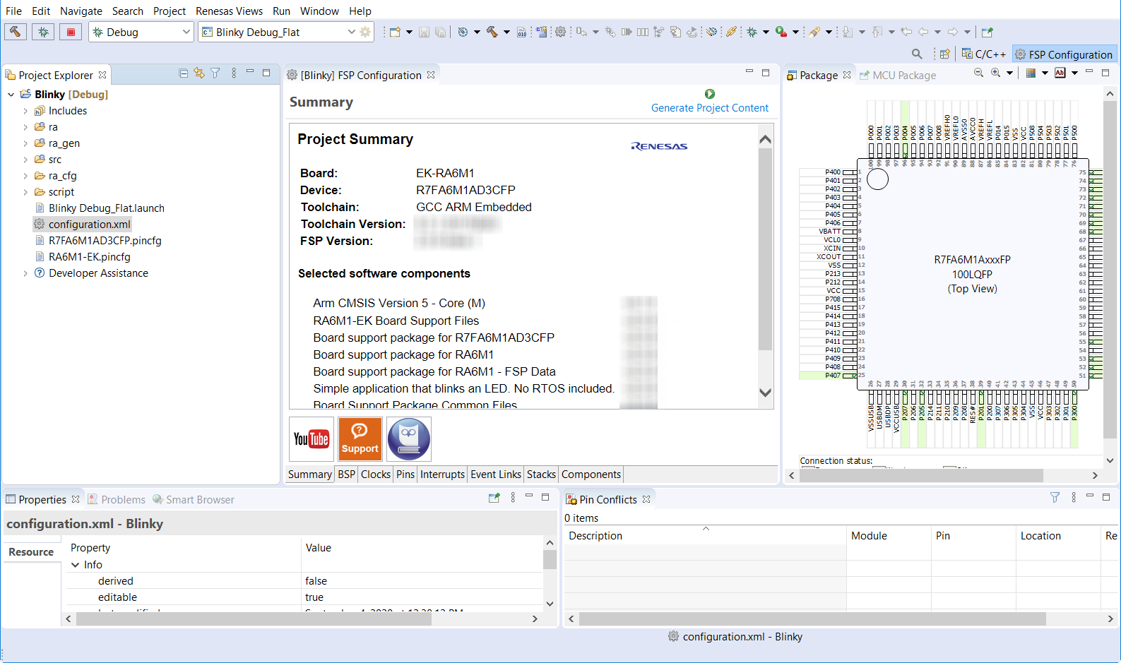
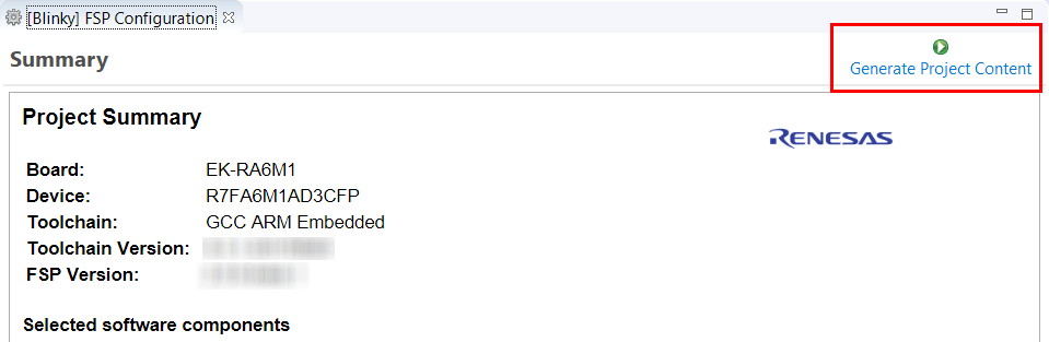
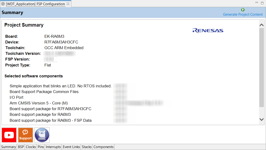
The Summary tab, seen in the above figure, identifies all the key elements and components of a project. It shows the target board, the device, toolchain and FSP version. Additionally, it provides a list of all the selected software components and modules used by the project. This is a more convenient summary view when compared to the Components tab.
The summary tab also includes handy icons with links to the Renesas YouTube channel, the Renesas support page and to the RA FSP User Manual that was downloaded during the installation process.
The BSP tab shows the currently selected board (if any) and device. The Properties view is located in the lower left of the Project Configurations view as shown below.
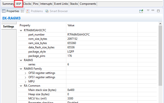
The Properties view shows the configurable options available for the BSP. These can be changed as required. The BSP is the FSP layer above the MCU hardware. e² studio checks the entry fields to flag invalid entries. For example, only valid numeric values can be entered for the stack size.
When you click the Generate Project Content button, the BSP configuration contents are written to ra_cfg/fsp_cfg/bsp/bsp_cfg.h
This file is created if it does not already exist.
The Clocks tab presents a graphical view of the MCU's clock tree, allowing the various clock dividers and sources to be modified. If a clock setting is invalid, the offending clock value is highlighted in red. It is still possible to generate code with this setting, but correct operation cannot be guaranteed. In the figure below, the USB clock UCLK has been changed so the resulting clock frequency is 60 MHz instead of the required 48 MHz. This parameter is colored red.
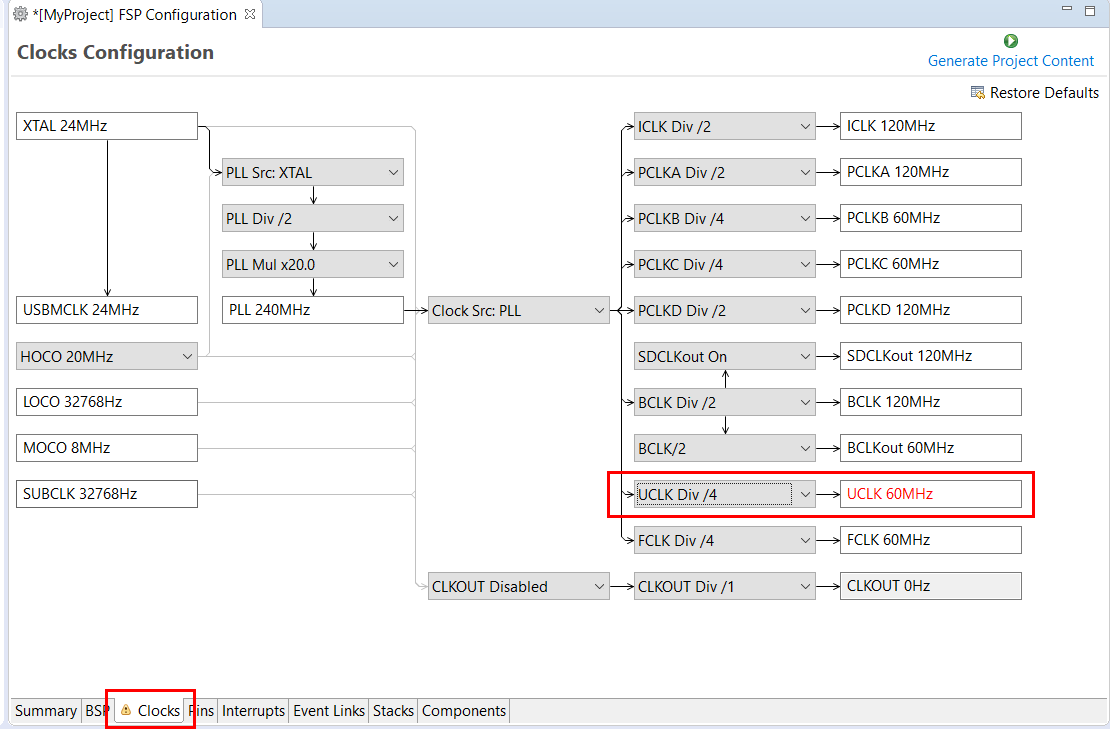
When you click the Generate Project Content button, the clock configuration contents are written to: ra_gen/bsp_clock_cfg.h
This file will be created if it does not already exist.
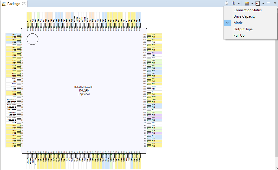
The Pins tab provides flexible configuration of the MCU's pins. As many pins are able to provide multiple functions, they can be configured on a peripheral basis. For example, selecting a serial channel via the SCI peripheral offers multiple options for the location of the receive and transmit pins for that module and channel. Once a pin is configured, it is shown as green in the Package view.
The Pins tab simplifies the configuration of large packages with highly multiplexed pins by highlighting errors and presenting the options for each pin or for each peripheral. If you selected a project template for a specific board such as the EK-RA6M3, some peripherals connected on the board are preselected.
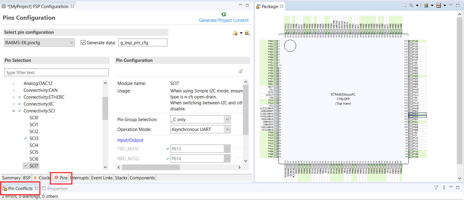
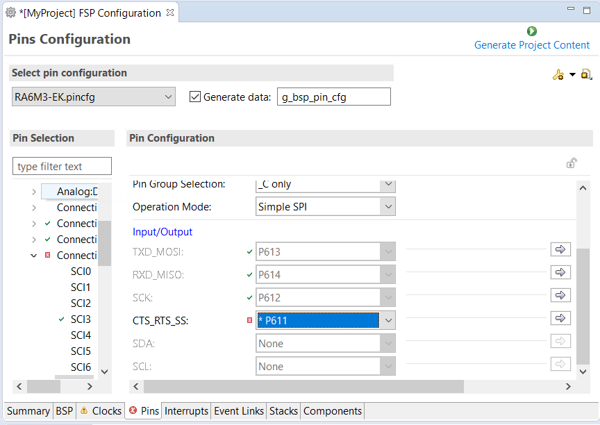
The pin configurator includes a built-in conflict checker, so if the same pin is allocated to another peripheral or I/O function the pin will be shown as red in the package view and also with white cross in a red square in the Pin Selection pane and Pin Configuration pane in the main Pins tab. The Pin Conflicts view provides a list of conflicts, so conflicts can be quickly identified and fixed.
In the example shown below, port P611 is already used by the CAC, and the attempt to connect this port to the Serial Communications Interface (SCI) results in a dangling connection error. To fix this error, select another port from the pin drop-down list or disable the CAC in the Pin Selection pane on the left side of the tab.
The pin configurator also shows a package view and the selected electrical or functional characteristics of each pin.
When you click the Generate Project Content button, the pin configuration contents are written to: ra_gen\bsp_pin_cfg.h
This file will be created if it does not already exist.
To make it easy to share pinning information for your project, e² studio exports your pin configuration settings to a csv format and copies the csv file to ra_gen/<MCU package>.csv.
You can use the Properties view in the Stacks tab to enable interrupts by setting the interrupt priority. Select the driver in the Stacks pane to view and edit its properties.
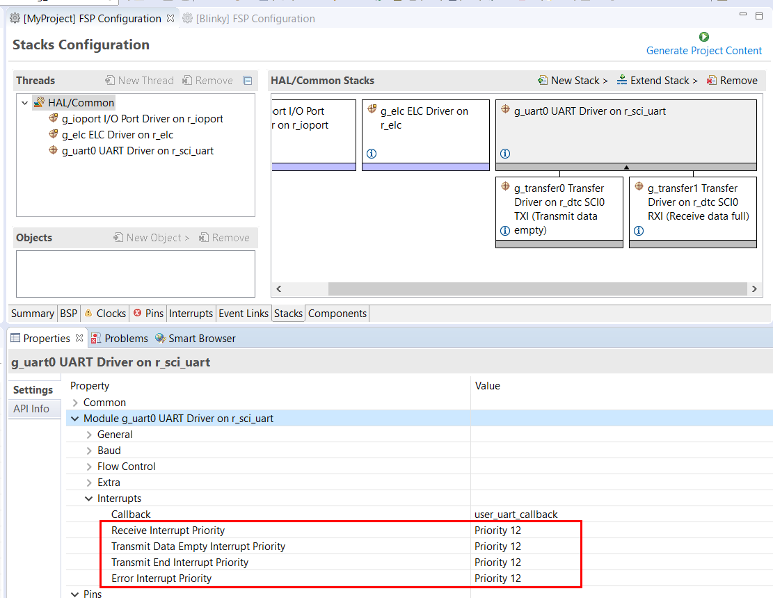
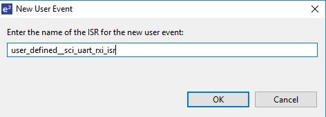
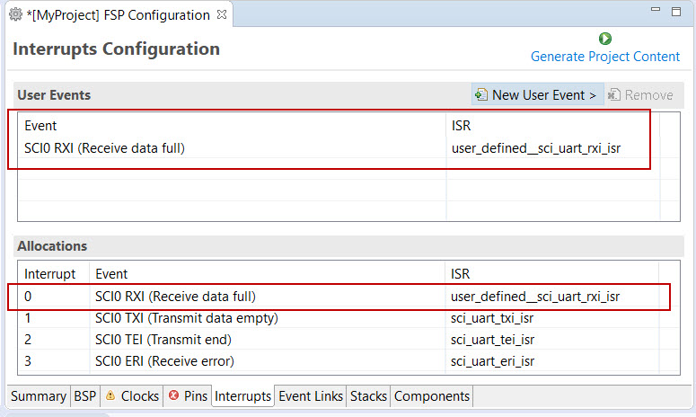
On the Interrupts tab, the user can bypass a peripheral interrupt set by FSP by setting a user-defined ISR. This can be done by adding a new event via the New User Event button.
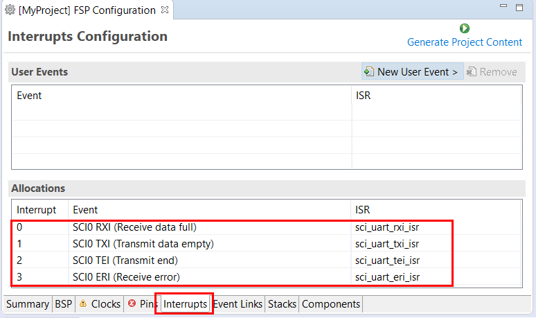
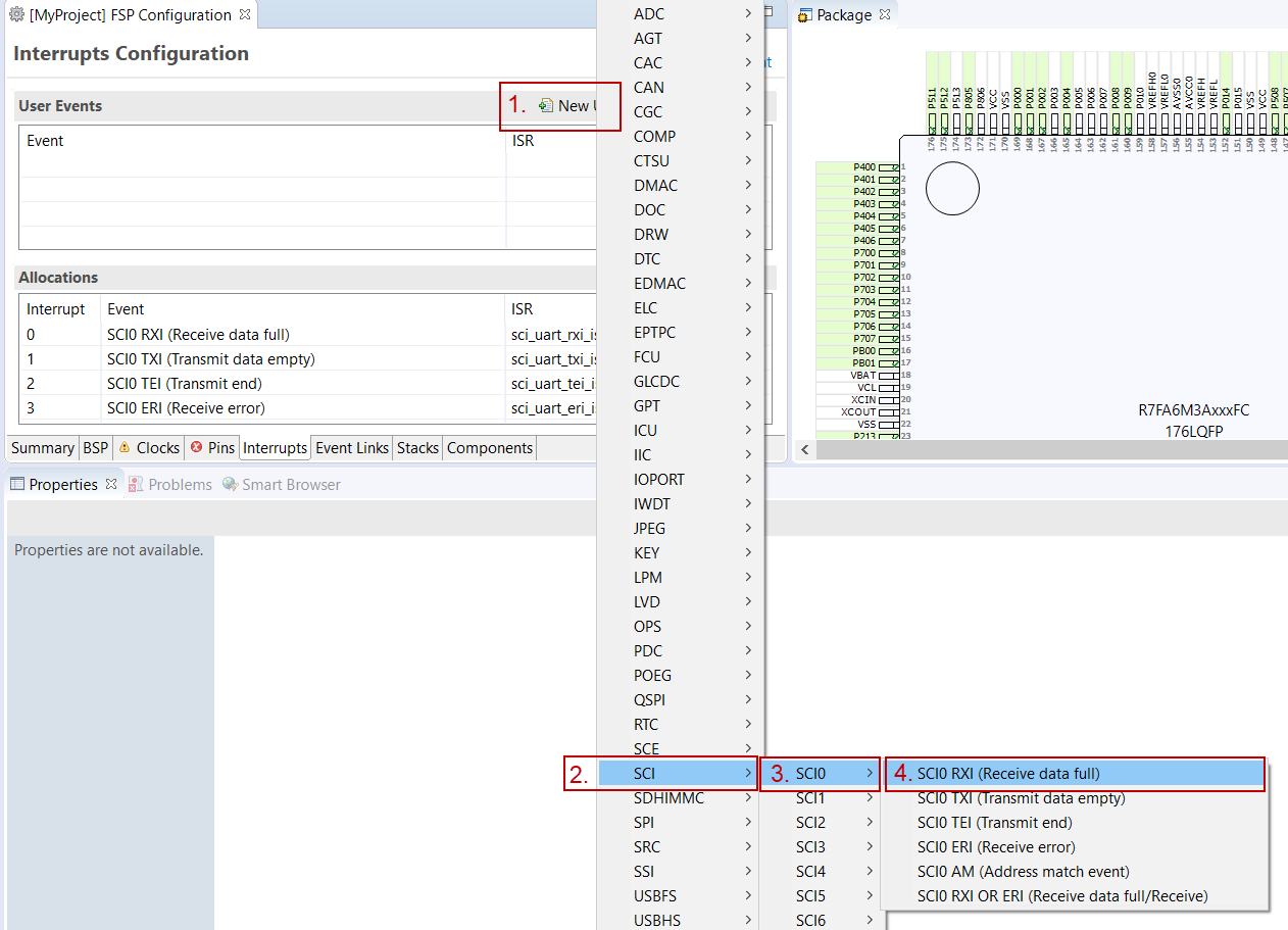
Enter the name of ISR for the new user event.
The Event Links tab can be used to view the Event Link Controller events. The events are sorted by peripheral to make it easy to find and verify them.
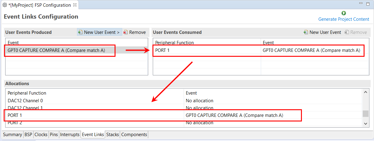
Like the Interrupts tab, user-defined event sources and destinations (producers and consumers) can be defined by clicking the relevant New User Event button. Once a consumer is linked to a producer the link will appear in the Allocations section at the bottom.
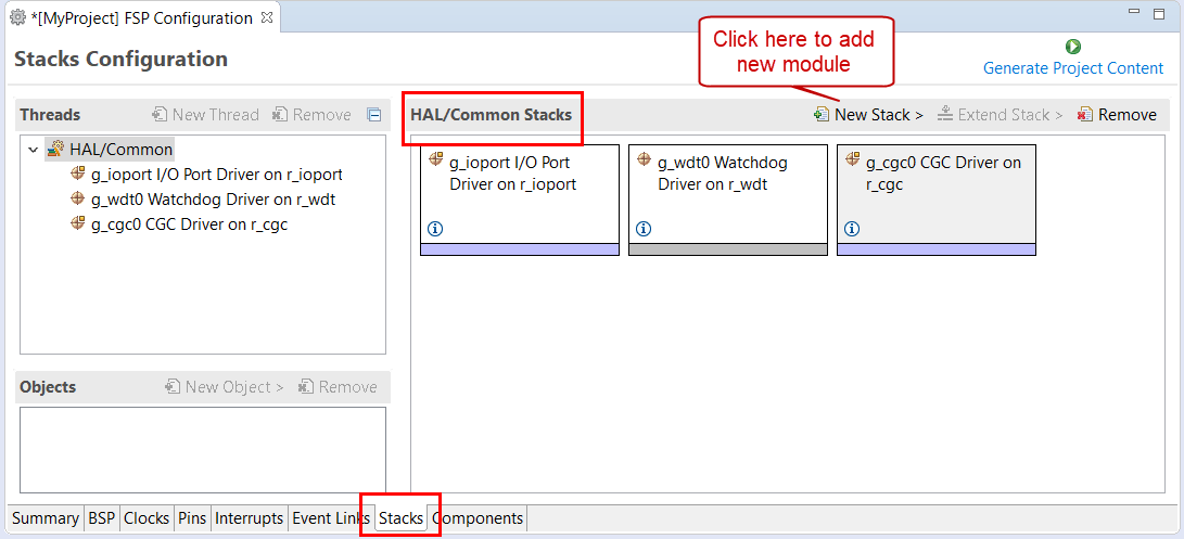
Every RTOS-based RA Project includes at least one RTOS Thread and a stack of FSP modules running in that thread. The Stacks tab is a graphical user interface which helps you to add the right modules to a thread and configure the properties of both the threads and the modules associated with each thread. Once you have configured the thread, e² studio automatically generates the code reflecting your configuration choices.
For any driver, or, more generally, any module that you add to a thread, e² studio automatically resolves all dependencies with other modules and creates the appropriate stack. This stack is displayed in the Stacks pane, which e² studio populates with the selected modules and module options for the selected thread.
The default view of the Stacks tab includes a Common Thread called HAL/Common. This thread includes the driver for I/O control (IOPORT). The default stack is shown in the HAL/Common Stacks pane. The default modules added to the HAL/Common driver are special in that FSP only requires a single instance of each, which e² studio then includes in every user-defined thread by default.
In applications that do not use an RTOS or run outside of the RTOS, the HAL/Common thread becomes the default location where you can add additional drivers to your application.
For a detailed description on how to add and configure modules and stacks, see the following sections:
Once you have added a module either to HAL/Common or to a new thread, you can access the driver's configuration options in the Properties view. If you added thread objects, you can access the objects configuration options in the Properties view in the same way.
You can find details about how to configure threads here: Configuring Threads
For applications that run outside or without the RTOS, you can add additional HAL drivers to your application using the HAL/Common thread. To add drivers, follow these steps:
Click on the HAL/Common icon in the Stacks pane. The Modules pane changes to HAL/Common Stacks.
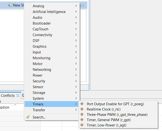
Select a driver from the menu New Stack > Driver.
e² studio adds the following files when you click the Generate Project Content button:
ra/fsp directorymain() function and configuration structures and header files for your application as shown in the table below.| File | Contents | Overwritten by Generate Project Content? |
|---|---|---|
| ra_gen/main.c | Contains main() calling generated and user code. When called, the BSP already has Initialized the MCU. | Yes |
| ra_gen/hal_data.c | Configuration structures for HAL Driver only modules. | Yes |
| ra_gen/hal_data.h | Header file for HAL driver only modules. | Yes |
| src/hal_entry.c | User entry point for HAL Driver only code. Add your code here. | No |
The configuration header files for all included modules are created or overwritten in this folder: ra_cfg/fsp_cfg
For an application that uses the RTOS, you can add one or more threads, and for each thread at least one module that runs in the thread. You can select modules from the Driver dropdown menu. To add modules to a thread, follow these steps:
In the Threads pane, click New Thread to add a Thread.
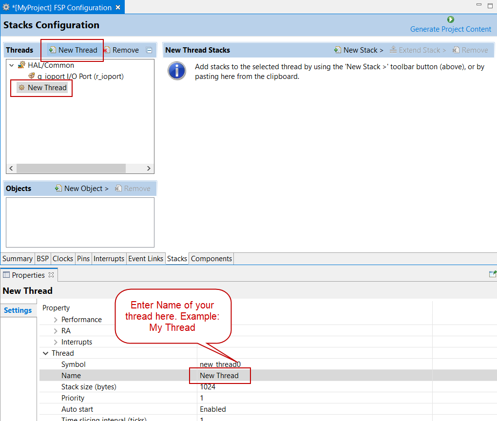
In the Properties view, click on the Name and Symbol entries and enter a distinctive name and symbol for the new thread.
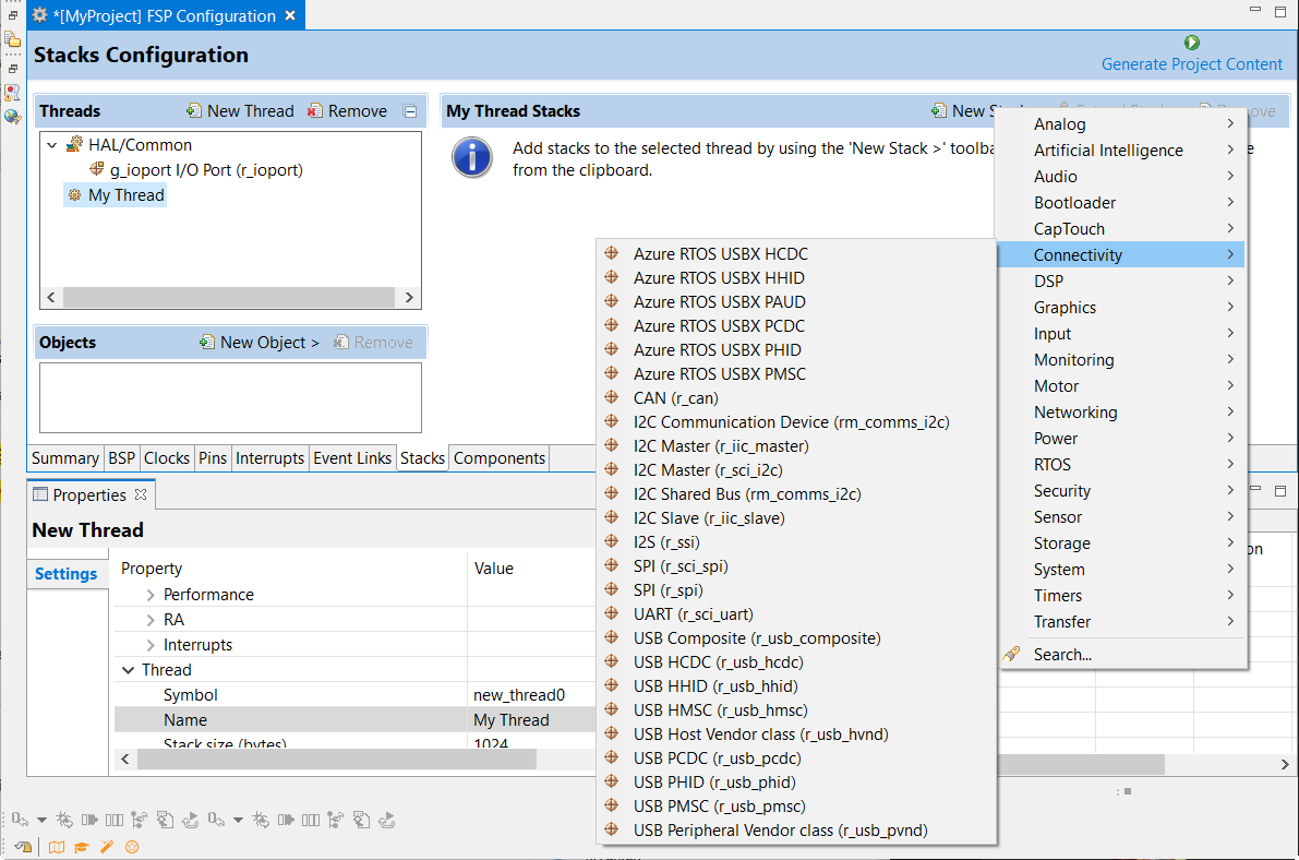
In the My Thread Stacks pane, click on New Stack to see a list of modules and drivers. HAL-level drivers can be added here.
Click on the added driver and configure the driver as required by the application by updating the configuration parameters in the Properties view. To see the selected module or driver and be able to edit its properties, make sure the Thread containing the driver is highlighted in the Threads pane.
When you press the Generate Project Content button for the example above, e² studio creates the files as shown in the following table:
| File | Contents | Overwritten by Generate Project Content? |
|---|---|---|
| ra_gen/main.c | Contains main() calling generated and user code. When called the BSP will have initialized the MCU. | Yes |
| ra_gen/my_thread.c | Generated thread "my_thread" and configuration structures for modules added to this thread. | Yes |
| ra_gen/my_thread.h | Header file for thread "my_thread" | Yes |
| ra_gen/hal_data.c | Configuration structures for HAL Driver only modules. | Yes |
| ra_gen/hal_data.h | Header file for HAL Driver only modules. | Yes |
| src/hal_entry.c | User entry point for HAL Driver only code. Add your code here. | No |
| src/my_thread_entry.c | User entry point for thread "my_thread". Add your code here. | No |
The configuration header files for all included modules and drivers are created or overwritten in the following folders: ra_cfg/fsp_cfg/<header files>
If the application uses an RTOS, the Stacks tab can be used to simplify the creation of RTOS threads, semaphores, mutexes, and event flags.
The components of each thread can be configured from the Properties view as shown below.
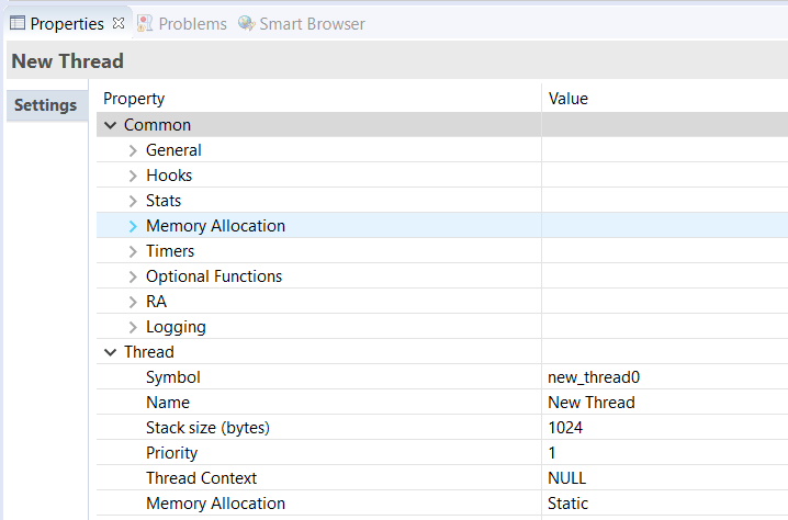
The Properties view contains settings common for all Threads (Common) and settings for this particular thread (Thread).
For this thread instance, the thread's name and properties (such as priority level or stack size) can be easily configured. e² studio checks that the entries in the property field are valid. For example, it will verify that the field Priority, which requires an integer value, only contains numeric values between 0 and 9.
To add RTOS resources to a Thread, select a thread and click on New Object in the Thread Objects pane. The pane takes on the name of the selected thread, in this case My Thread Objects.
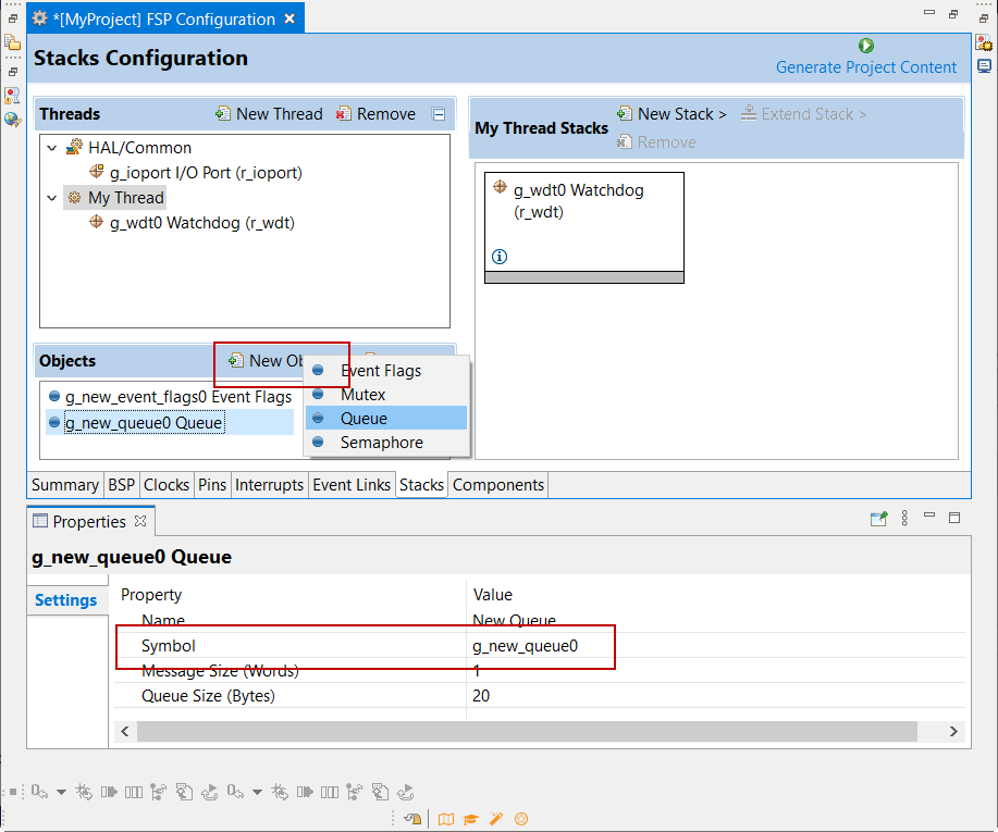
Make sure to give each thread object a unique name and symbol by updating the Name and Symbol entries in the Properties view.
The Components tab enables the individual modules required by the application to be included or excluded. Modules common to all RA MCU projects are preselected (for example: BSP > BSP > Board-specific BSP and HAL Drivers > all > r_cgc). All modules that are necessary for the modules selected in the Stacks tab are included automatically. You can include or exclude additional modules by ticking the box next to the required component.
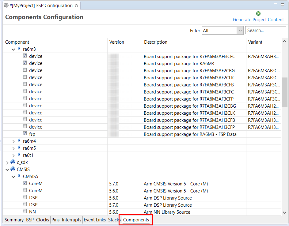
Clicking the Generate Project Content button copies the .c and .h files for each selected component into the following folders:
ra/fsp/inc/apira/fsp/inc/instancesra/fsp/src/bspra/fsp/src/<Driver_Name>e² studio also creates configuration files in the ra_cfg/fsp_cfg folder with configuration options set in the Stacks tab.
Once you have added Modules and drivers and set their configuration parameters in the Stacks tab, you can add the application code that calls the Modules and drivers.
e² studio provides several efficiency improving features that help write code. Review these features prior to digging into the code development step-by-step sections that follow.
Autocomplete is a context aware coding accelerator that suggests possible completions for partially typed-in code elements. If you can 'guess' the first part of a macro, for example, the Autocomplete function can suggest options for completing the rest of the macro.
In the following example, a macro related to a BSP_IO setting needs to be found. After typing BSP_IO_ in a source code file, pressing Ctrl + Space opens the Autocomplete list. This list shows a selection of context aware options for completing the macro. Scroll through the window to find the desired macro (in this case BSP_IO_LEVEL_HIGH) and click on it to add it to your code.
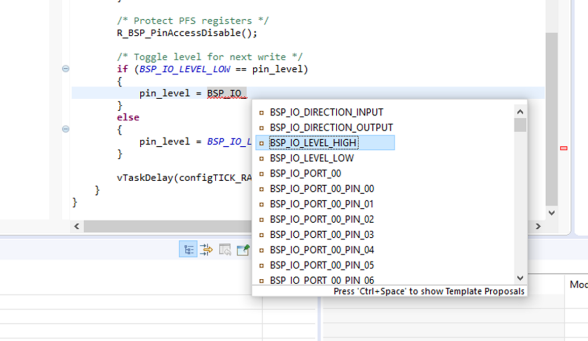
Other code elements can use autocomplete too. Some of the more common uses for Autocomplete include Enumerations, Types, and API functions - but try it in any situation you think the tool may have enough context to determine what you might be looking for.
For a hands-on experience using Autocomplete use the Quick FSP Labs for Creating Blinky from Scratch and Creating an RTC Blinky from Scratch. These 15-minute Do it Yourself labs take you through the step-by-step process of using Autocomplete, Developer Assistance, and the Help system.
The e² studio Welcome window displays useful information and common links to assist in development. Check out these resources to see what is available. They are updated with each release, so check back to see what has been added after a new release.
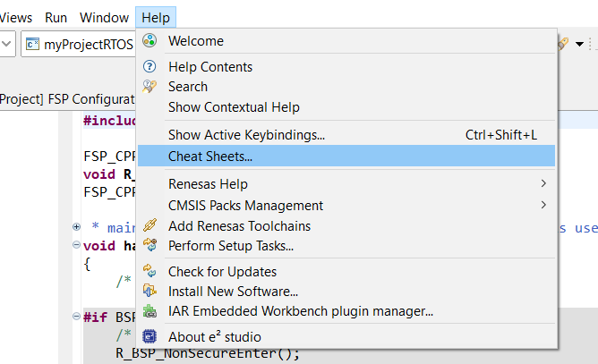
Cheat sheets are macro driven illustrations of some common tasks. They show, step-by-step, what commands and menus are used. These will be populated with more examples on each release. Cheat Sheets are available from the Help menu.
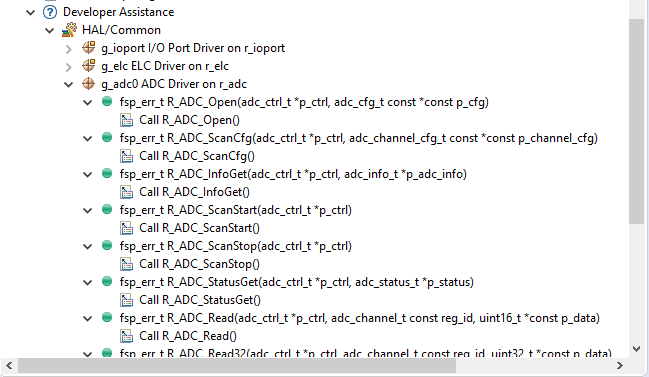
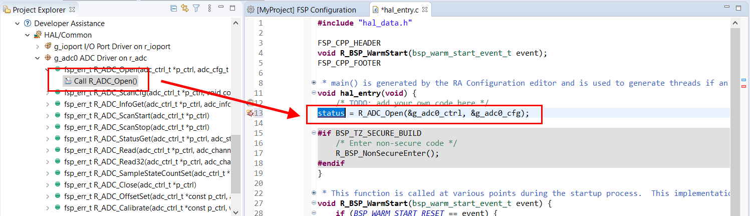
FSP Developer Assistance provides developers with module and Application Programming Interface (API) reference documentation in e² studio. After configuring the threads and software stacks for an FSP project with the RA Configuration editor, Developer Assistance quickly helps you get started writing C/C++ application code for the project using the configured stack modules.
Expand the project explorer to view Developer Assistance
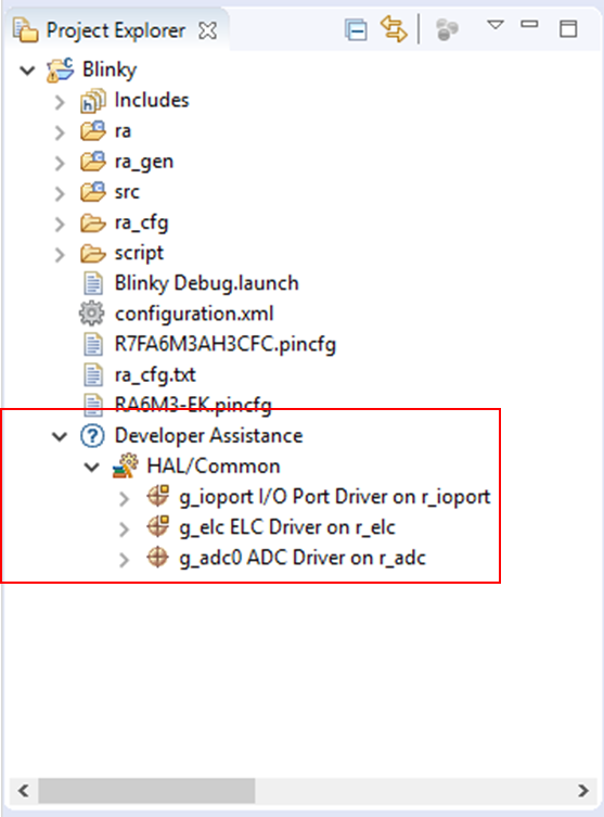
Expand a stack module to show its APIs
For a hands-on experience using Developer Assistance use the Quick FSP Labs for An Introduction to Developer Assistance, Creating Blinky from Scratch and Creating an RTC Blinky from Scratch. These 15-minute Do it Yourself labs take you through the step-by-step process of using Autocomplete, Developer Assistance, and the Help system.
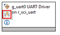
Information icons are available on each module in the thread stack. Clicking on these icons opens a module folder on GitHub that contains additional information on the module. An example information Icon is shown below:
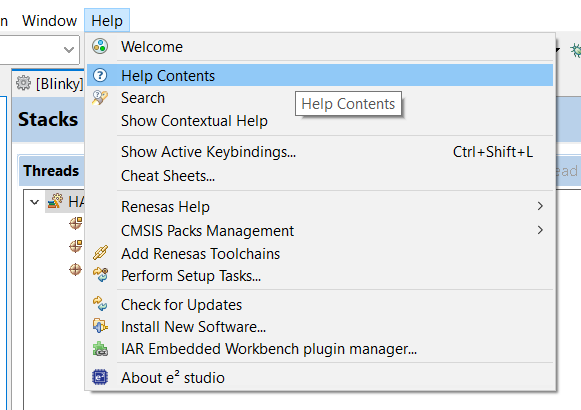
A good source of additional information for many FSP topics is the Help system. To get to the Help system, click on Help and then select Help Contents as seen below.
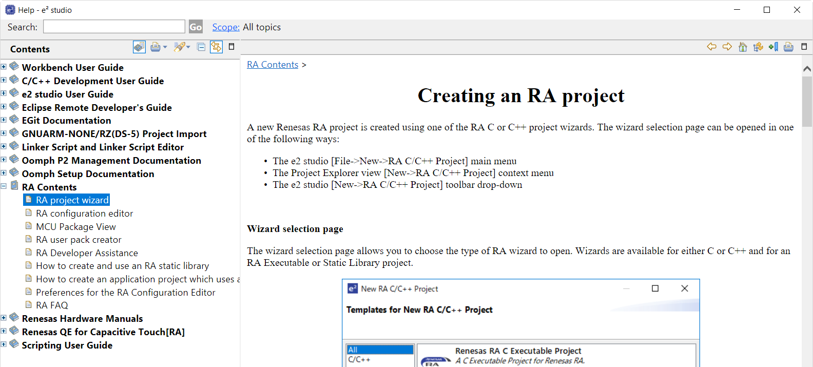
Once the Help system is open, select the RA Contents entry in the left side Guide-bar. Expand it to see the main RA Topics.
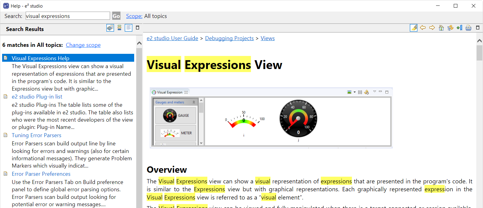
You can also search for help topics by using the Search bar. Below is an example searching for Visual Expressions, a helpful feature in the e² studio debugger.
For a hands-on experience using the Help system use the Quick FSP Labs for An Introduction to Developer Assistance, Creating Blinky from Scratch and Creating an RTC Blinky from Scratch. These 15-minute Do it Yourself labs take you through the step-by-step process of using Autocomplete, Developer Assistance, and the Help system.
The FSP Architecture section describes FSP stacks, modules and interfaces in significant detail, providing an understanding of the theory behind them. The following sections provides a quick and practical introduction on how to use API functions when writing code and where in the API reference sections you can find useful API related information.
In FSP, HAL module drivers provide convenient API functions that access RA processor peripheral features. Module properties are defined in the RA GUI configurator, eliminating the tedious and error prone process of setting peripheral control registers. When configuration is complete, the generator automatically creates the code needed to implement the associated API functions. API functions are the main way a developer interacts with the target processor and peripherals.
HAL driver API functions all have a similar format. They all start with "R_" to indicate they are HAL related functions. Next comes the module name followed by the function and any parameters. This format is illustrated below:
Here are some examples:
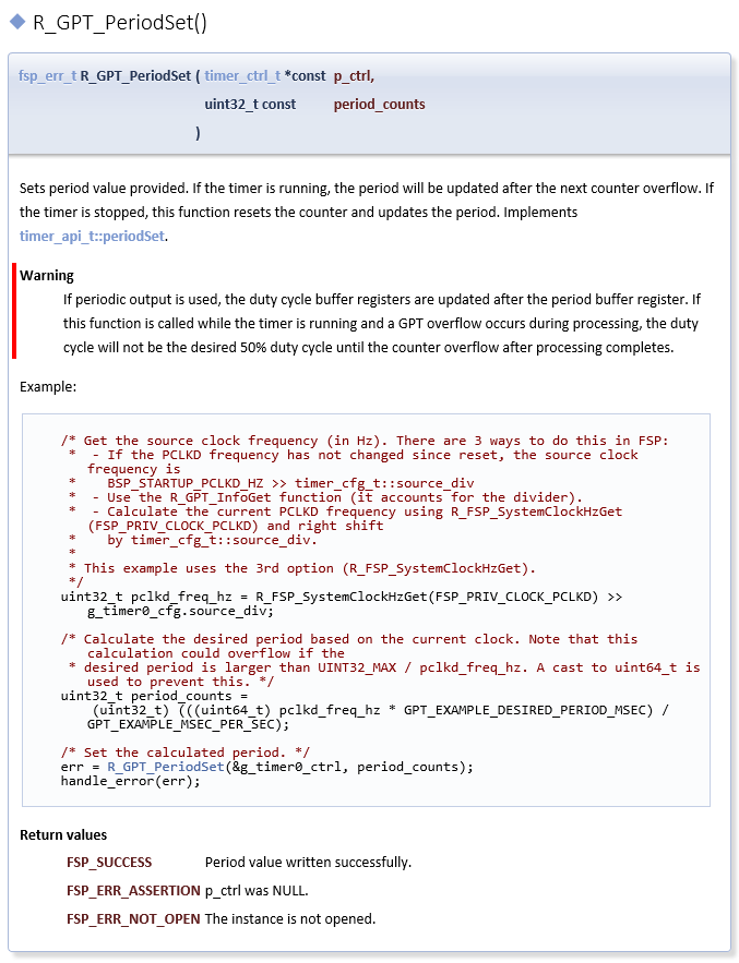
Each HAL module has a useful API Reference section that includes key details on each function. The function prototype is presented first, showing the return type (usually fsp_status_t for HAL functions) and the function parameters. A short description and any warnings or notes follow the function definition. In some cases, a code snippet is included to illustrate use of the function. Finally, all possible return values are provided to assist in debugging and error management.
To write application code:
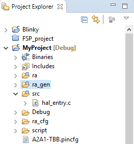
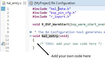
In the Project Explorer view, double-click on the src/hal_entry.c file to edit the source file.
ra_gen/hal_data.c.Add your application code here:
The following tutorial shows how execute the steps above and add application code: Tutorial: Using HAL Drivers - Programming the WDT.
The WDT example is a HAL level application which does not use an RTOS. The user guides for each module also include basic application code that you can add to hal_entry.c.
To write RTOS-aware application code using RTOS, follow these steps:
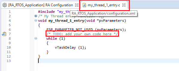
In the Project Explorer view, double-click on the src/my_thread_1_entry.c file to edit the source file.
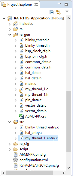
ra_gen/my_thread_1.c and my_thread_2.cra_gen. These files are overwritten every time you push the Generate Project Content button.Add your application code here:
A wide variety of Example Projects for FSP and RA MCUs is available on the GitHub site here: https://github.com/renesas/ra-fsp-examples. Example projects are organized by target kit so it is easy to find all the examples for your kit of choice.
Projects are available as both downloadable zip files and as project source files. Typically, there is a project for each module. New example projects are being added periodically, so check back if a particular module isn't yet available.
A variety of Hands-on Do It Yourself labs are available on the Renesas RA and FSP Knowledge Base. Quick FSP Labs target the EK-RA6M3 kit and typically require only 15 minutes to complete. Each lab covers a couple related development tools and techniques like Autocomplete, Developer Assistance, console I/O over RTT, and Visual Expressions, that can speed up the development process. A list of all available Quick Labs can be found here: https://en-support.renesas.com/knowledgeBase/19450948
Once your project builds without errors, you can use the Debugger to download your application to the board and execute it.
To debug an application follow these steps:
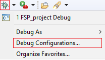
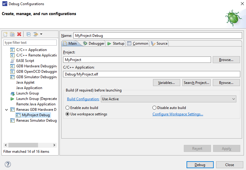
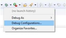
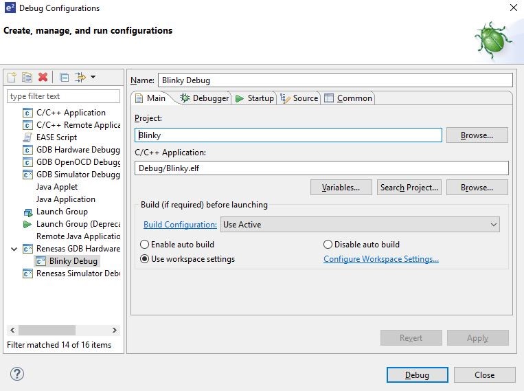
On the drop-down list next to the debug icon, select Debug Configurations.
In the Debug Configurations view, click on your project listed as MyProject Debug.
There are instances where it may be necessary to make changes to the toolchain being used (for example, to change optimization level of the compiler or add a library to the linker). Such modifications can be made from within e² studio through the menu Project > Properties > C/C++ Build > Settings when the project is selected. The following screenshots show the settings dialogs for the GNU Arm and LLVM toolchains. The dialog looks slightly different depending upon the toolchain being used.
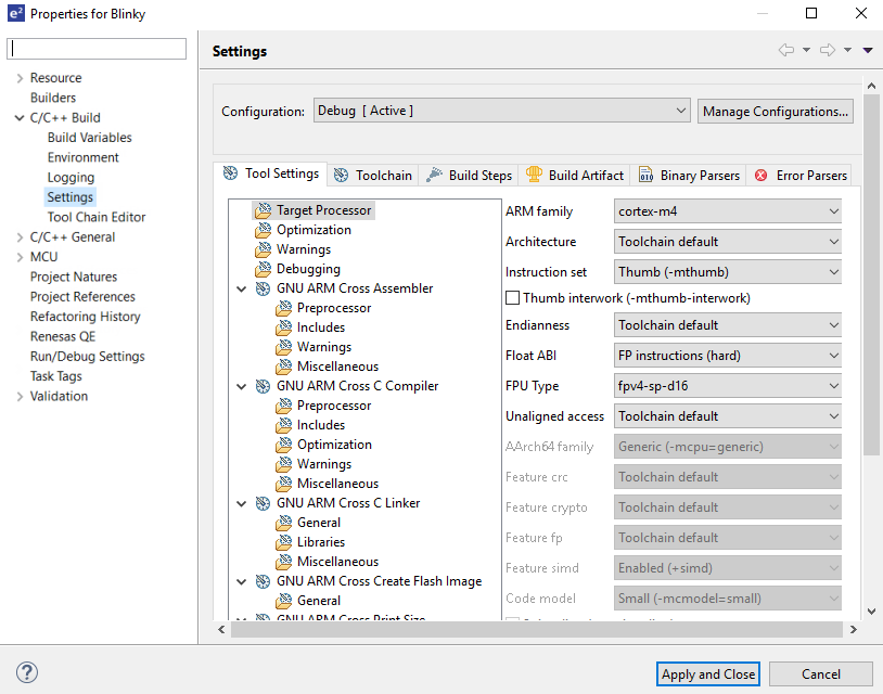
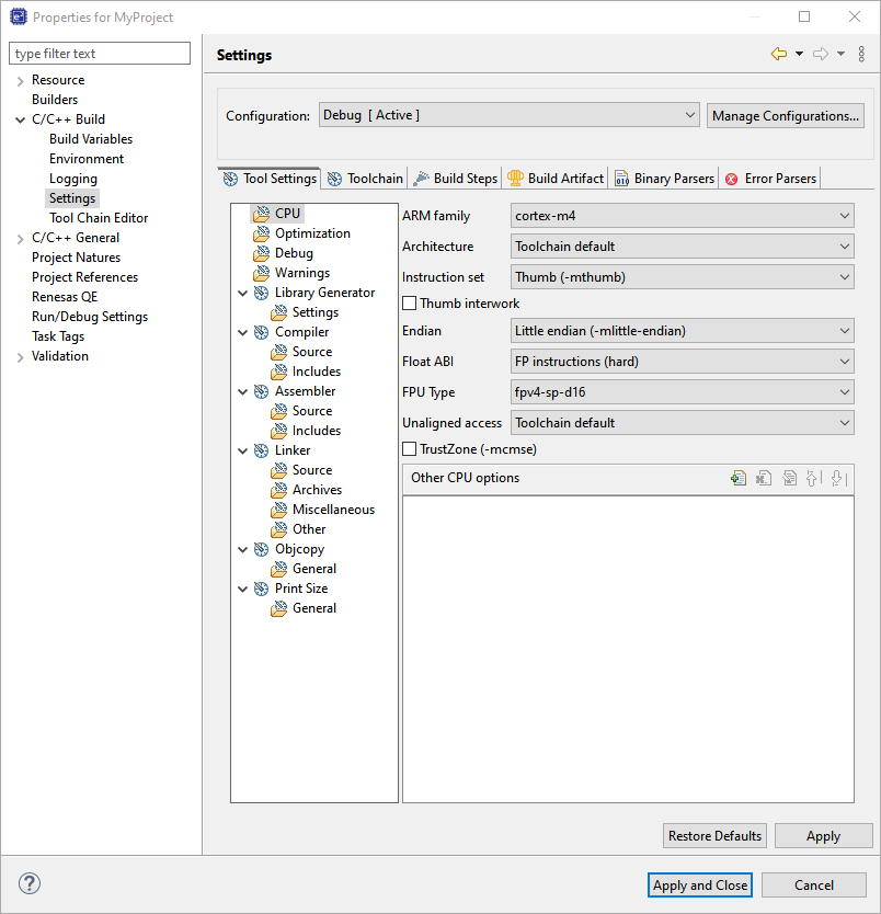
The scope for the settings is project scope which means that the settings are valid only for the project being modified.
The settings for the linker which control the location of the various memory sections are contained in a script file specific for the device being used. This script file is included in the project when it is created and is found in the script folder (for example, /script/a6m3.ld).
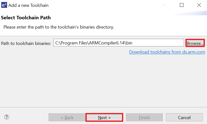
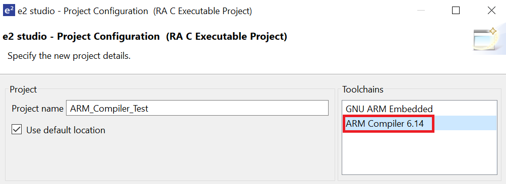
e² studio does not include the Arm Compiler 6 (AC6) toolchain by default. Follow the steps below to integrate AC6 into e² studio and create an AC6 RA project.
Steps 1 through 8 describe the process for integrating Arm Compiler 6 into e² studio.
Click Add.
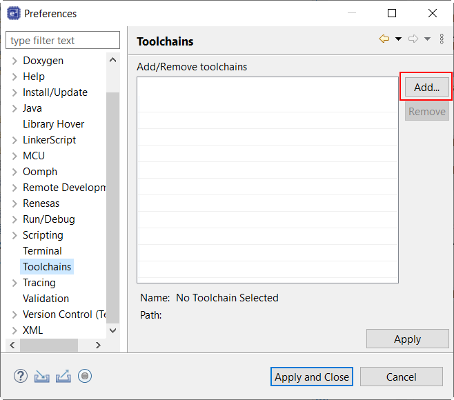
Browse to the path where AC6 toolchain is installed and select the \bin folder. Click Next.
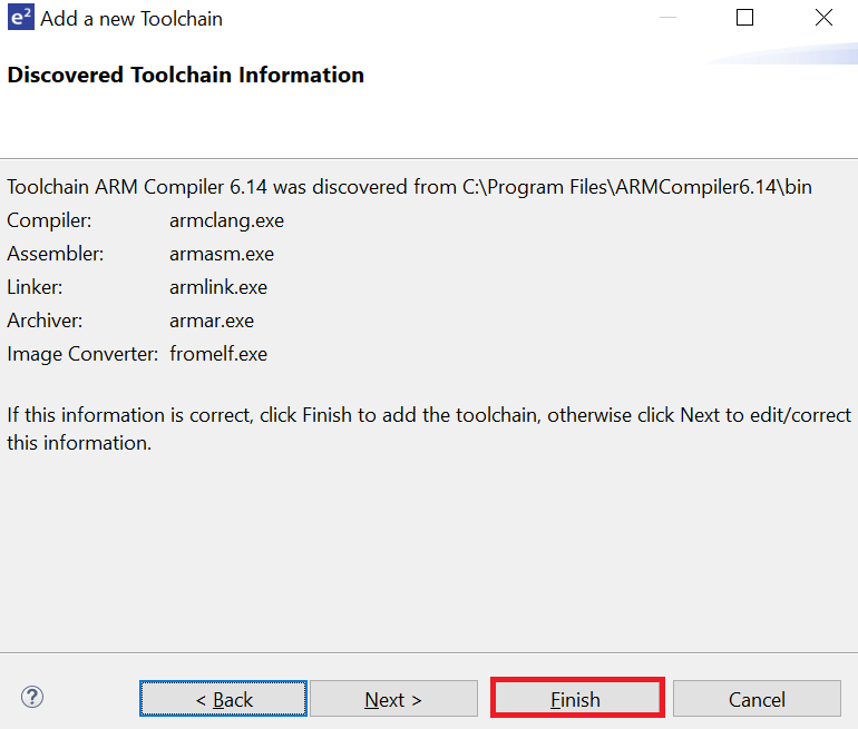
Toolchain information in displayed. Click Finish.
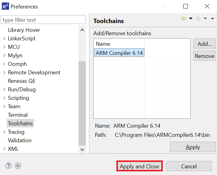
Click Apply and Close.
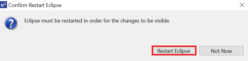
Click Restart Eclipse when prompted.
When creating a new RA C/C++ project, select ARM Compiler 6 included in the Toolchains section.
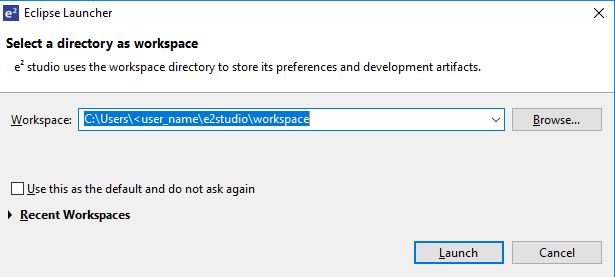
At the end of e² studio startup, you will see the Workspace Launcher Dialog box as shown in the following figure.
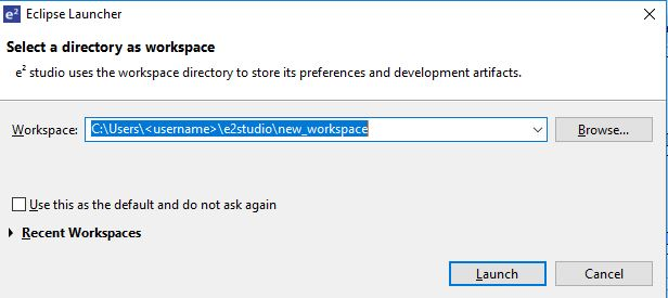
Enter a new workspace name in the Workspace Launcher Dialog as shown in the following figure. e² studio creates a new workspace with this name.
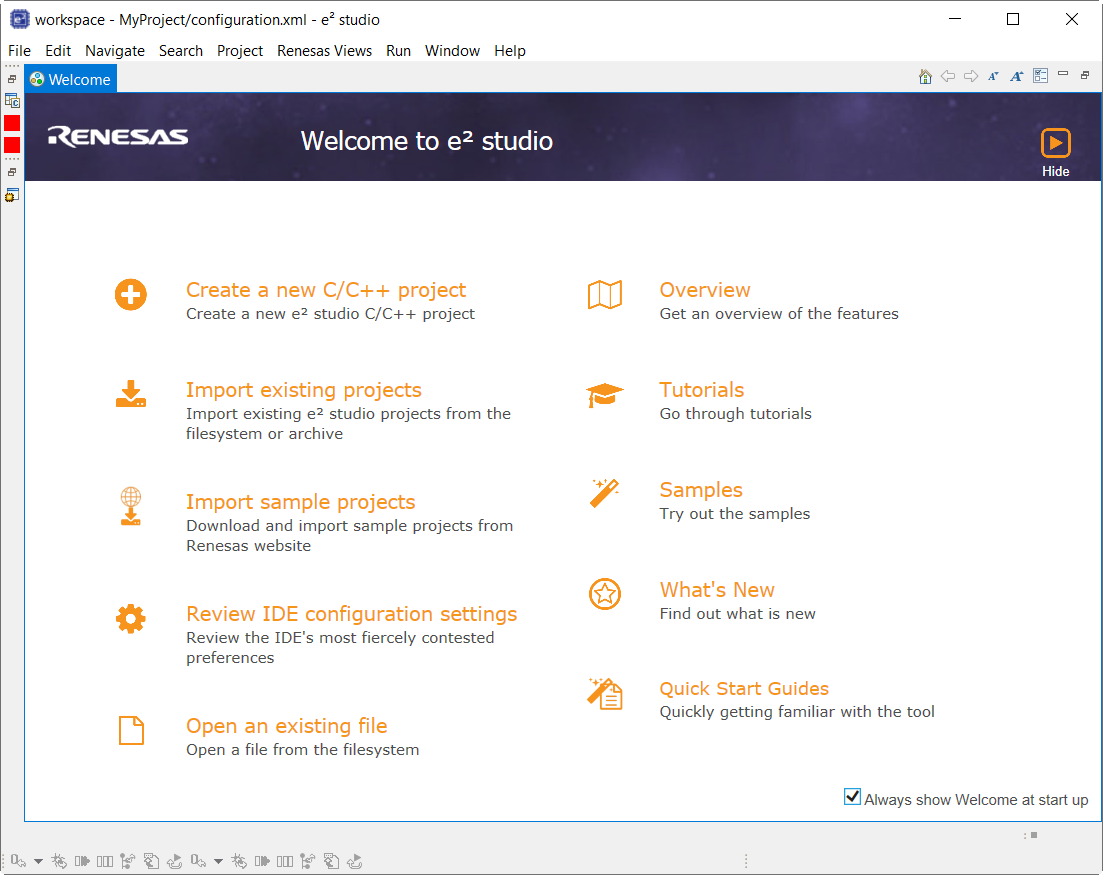
When the workspace is opened, you may see the Welcome Window. Click on the Hide arrow button to proceed past the Welcome Screen as seen in the following figure.
You are now in the workspace that you want to import the project into. Click the File menu in the menu bar, as shown in the following figure.
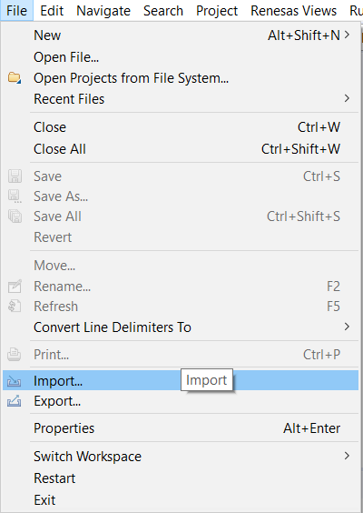
Click Import on the File menu or in the menu bar, as shown in the following figure.
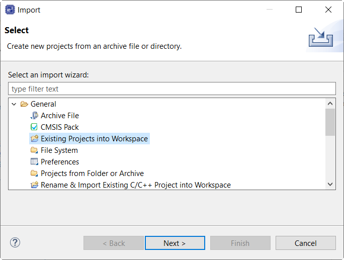
In the Import dialog box, as shown in the following figure, choose the General option, then Existing Projects into Workspace, to import the project into the current workspace.
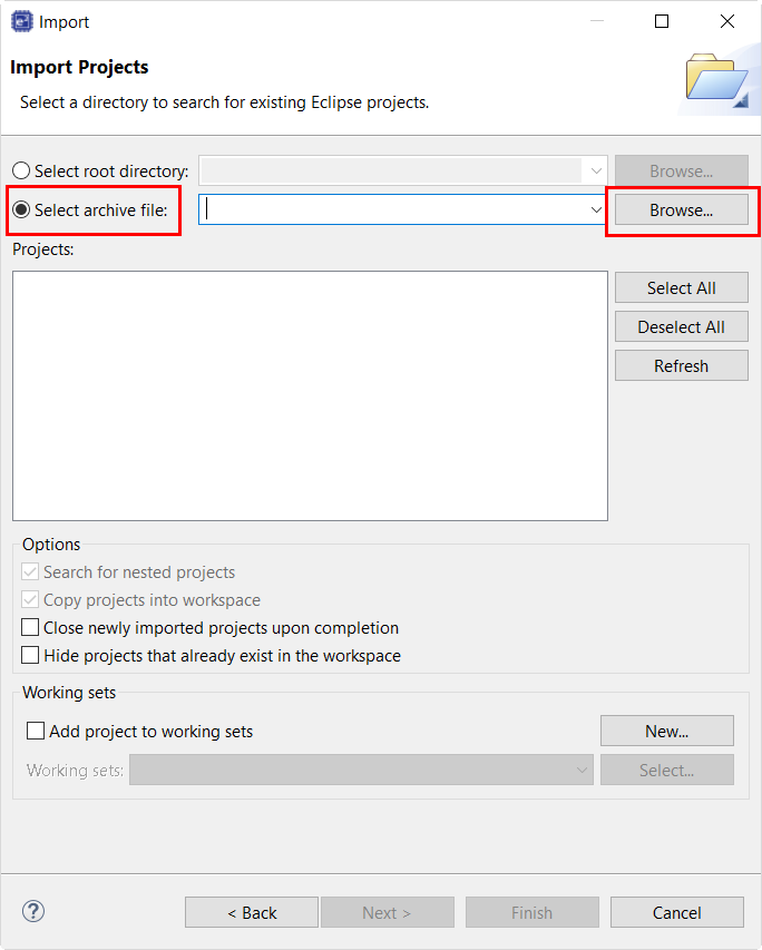
Click Select archive file as shown in the following figure.
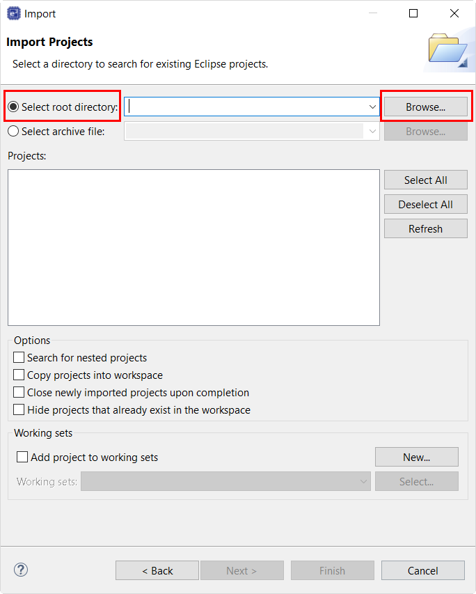
Click Select root directory as shown in the following figure.
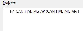
CAN_HAL_MG_AP.zip or CAN_HAL_MG_AP.Select the project to import from the list of Projects, as shown in the following figure.
When using certain standard C I/O functions such as printf and scanf semihosting must be initialized for them to work correctly with the Renesas Debug Virtual Console. In order to setup semihosting a call to initialise_monitor_handles should be added somewhere in your application before any semihosting related calls are made. Here is an example declaration and call:
The goal of this tutorial is to quickly get acquainted with the Flexible Platform by moving through the steps of creating a simple application using e² studio and running that application on an RA MCU board.
The application used in this tutorial is Blinky, traditionally the first program run in a new embedded development environment.
Blinky is the "Hello World" of microcontrollers. If the LED blinks you know that:
The Blinky example application used in this tutorial is designed to run the same way on all boards offered by Renesas that hold the RA microcontroller. The code in Blinky is completely board independent. It does the work by calling into the BSP (board support package) for the particular board it is running on. This works because:
To follow this tutorial, you need:
The creation and configuration of an RA MCU project is the first step in the creation of an application. The base RA MCU pack includes a pre-written Blinky example application that is simple and works on all Renesas RA MCU boards.
Follow these steps to create an RA MCU project:
Click Next. The Project Configuration window shows your selection.

Select the board support package by selecting the name of your board from the Device Selection drop-down list and click Next.
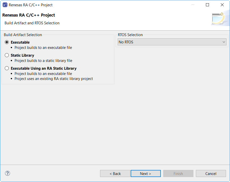
Select the build artifact and RTOS.
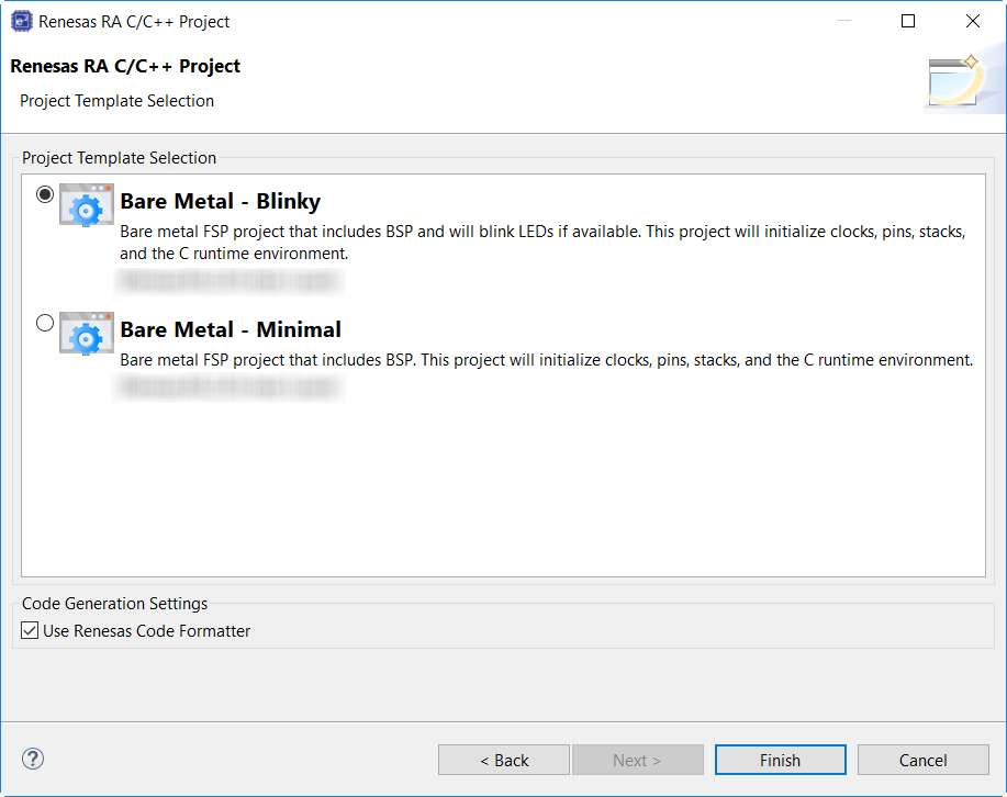
Select the Blinky template for your board and click Finish.
Once the project has been created, the name of the project will show up in the Project Explorer window of e² studio. Now click the Generate Project Content button in the top right corner of the Project Configuration window to generate your board specific files.
Your new project is now created, configured, and ready to build.
The Generate Project Content button creates configuration header files, copies source files from templates, and generally configures the project based on the state of the Project Configuration screen.
For example, if you check a box next to a module in the Components tab and click the Generate Project Content button, all the files necessary for the inclusion of that module into the project will be copied or created. If that same check box is then unchecked those files will be deleted.
By selecting the Blinky template, the clocks are configured by e² studio for the Blinky application. The clock configuration tab (see Configuring Clocks) shows the Blinky clock configuration. The Blinky clock configuration is stored in the BSP clock configuration file (see BSP Clock Configuration).
By selecting the Blinky template, the GPIO pins used to toggle the LED1 are configured by e² studio for the Blinky application. The pin configuration tab shows the pin configuration for the Blinky application (see Configuring Pins). The Blinky pin configuration is stored in the BSP configuration file (see BSP Pin Configuration).
The Blinky project automatically selects the following HAL components in the Components tab:
To see the configuration parameters for any of the components, check the Properties tab in the HAL window for the respective driver (see Adding and Configuring HAL Drivers).
The main function is located in < project >/ra_gen/main.c. It is one of the files that are generated during the project creation stage and only contains a call to hal_entry(). For more information on generated files, see Adding and Configuring HAL Drivers.
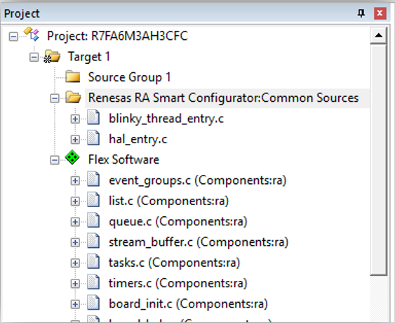
The blinky application is stored in the hal_entry.c file. This file is generated by e² studio when you select the Blinky Project template and is located in the project's src/ folder.
The application performs the following steps:
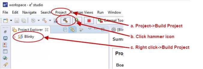
R_BSP_PinWrite((bsp_io_port_pin_t) pin, pin_level);Highlight the new project in the Project Explorer window by clicking on it and build it.
There are three ways to build a project:
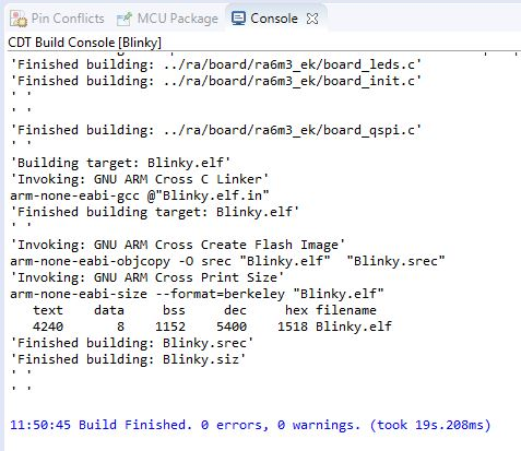
Once the build is complete a message is displayed in the build Console window that displays the final image file name and section sizes in that image.
To debug the project on a board, you need
Applications run from the internal flash of your microcontroller. To run or debug the application, the application must first be programmed to the microcontroller's flash. There are two ways to do this:
Some boards have an on-board JTAG debugger and others require an external JTAG debugger connected to a header on the board.
Refer to your board's user manual to learn how to connect the JTAG debugger to e² studio.
To debug the Blinky application, follow these steps:
Configure the debugger for your project by clicking Run > Debugger Configurations ...
or by selecting the drop-down menu next to the bug icon and selecting Debugger Configurations ...
Select your debugger configuration in the window. If it is not visible then it must be created by clicking the New icon in the top left corner of the window. Once selected, the Debug Configuration window displays the Debug configuration for your Blinky project.
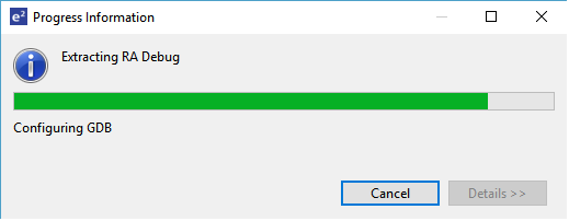
Extracting RA Debug.
In debug mode, e² studio executes the following tasks:
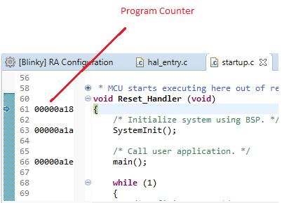
While in Debug mode, click Run > Resume or click on the Play icon twice.
The LEDs on the board marked LED1, LED2, and LED3 should now be blinking.
This section provides information on how to create and debug multicore projects using e² studio and FSP. It is recommended that users read the section Tutorial: Your First RA MCU Project - Blinky before this one. The multicore application created will consist of a single project for each core of an RA8P1. Multicore support was added to FSP in v6.0.0 and the features available will be expanding in future releases. This section will be updated as needed.
Note: This section assumes the user already has a working knowledge of normal (non-multicore) usage of RA FSP and e² studio.
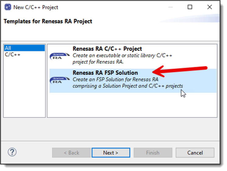
e² studio now offers a mechanism to generate a multicore project pair using a single run through the project wizard. This is accessed via the "Renesas RA FSP Solution" option (rather than using the traditional C/C++ Project option):
When this option is selected, a similar set of dialog pages to the standard wizard will then be displayed, but currently reduced in number and with fewer options available.
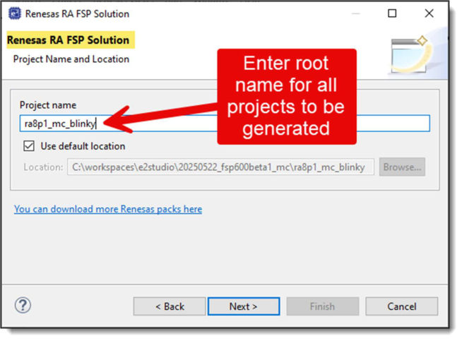
Enter a name that will be used for the Solution project and the prefix for individual core projects. For example, if you choose a project name of "my_application" for an RA MCU with 2 cores, then there will be 3 resulting projects: "my_application" (Solution), "my_application_CPU0", and "my_application_CPU1".
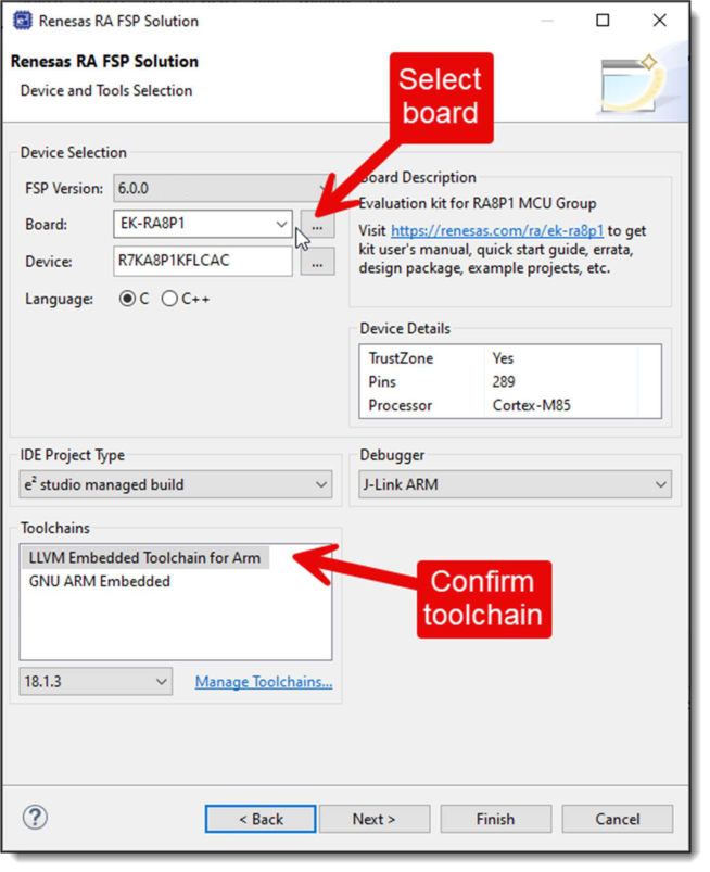
Choose the board you are using and confirm the toolchain you wish to use.
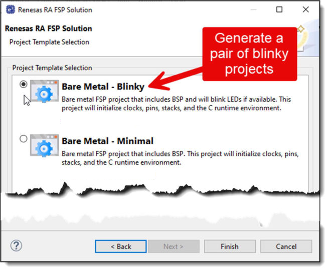
Choose the "Bare Metal - Blinky" project template. This template will be used for creating the projects for all cores.
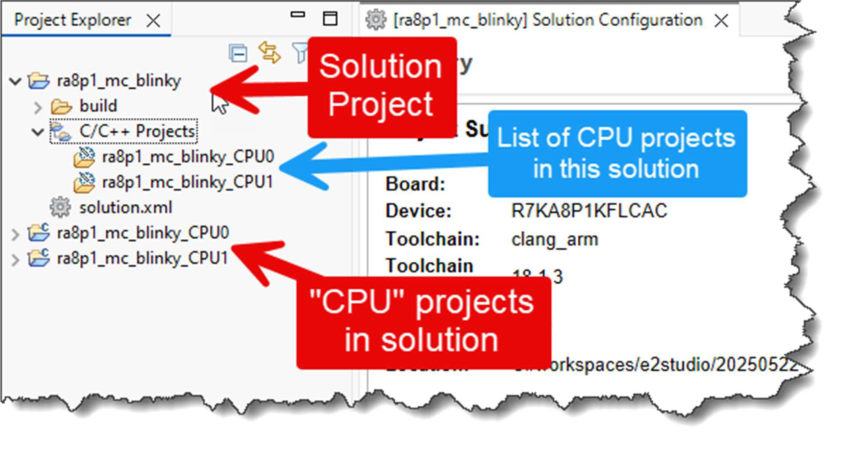
After clicking on the Finish button in the wizard, a set of projects will be generated with appropriate linkage between them. Two of the projects are “normal” projects independent to each core which, when combined, will generate the overall multicore application that will be downloaded to the target MCU. The third project is the "container" Solution project which contains and controls configuration of the overall MCU and the CPU projects.
Starting in FSP 6.0.0, the hal_entry.c file generated as part of the Blinky project template has been updated to support multicore projects. First, a call to the FSP inline function R_BSP_SecondaryCoreStart() (that starts execution of CPU1 by releasing it from reset) has been added to hal_entry() in the case that this file is being built for the primary core in a set of multicore projects.
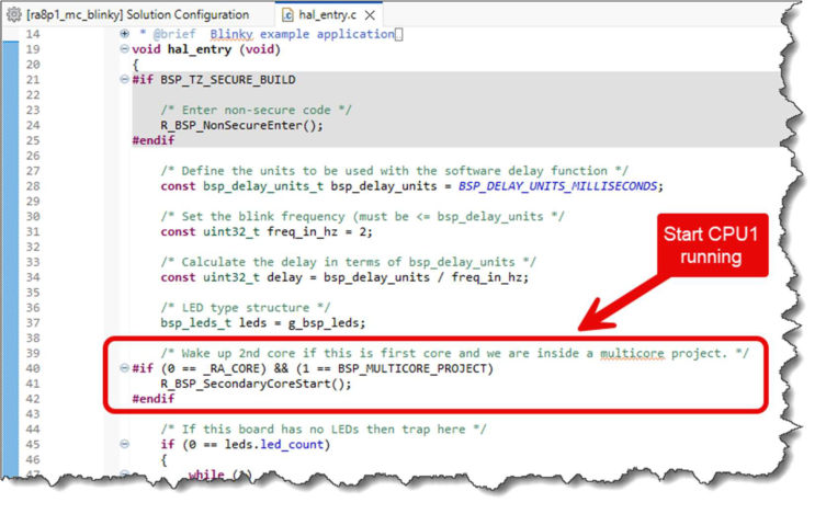
Second, the LED flashing code in hal_entry() has been changed so that it only blinks one of the LEDs for a multicore project (rather than all LEDs on the board).
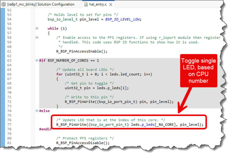
This means that for a multicore application the primary core (CPU0) will blink the first LED on the board and the secondary core (CPU1) will blink the second LED. This allows the user to easily tell which core or cores are currently active.
When a FSP Solution application is used, builds should always be triggered from the Solution project. The reason is that the Solution project stores information that is applicable to all downstream projects. Building from the Solution ensures that all the latest settings are propagated to each downstream project.
Although it is possible to start a debug session for CPU0 then manually start a second debug session for CPU1, it is easier to have e² studio do the two operations in one.
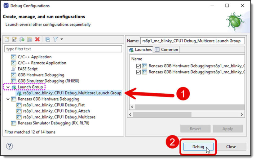
To enable this, the multicore solutions project wizard will create a "Launch Group" inside the CPU1 project containing the two individual launch configurations, one for each of the CPUs. This launch group is what will then be used to start a multicore debug session rather than the launch configurations themselves being used directly.
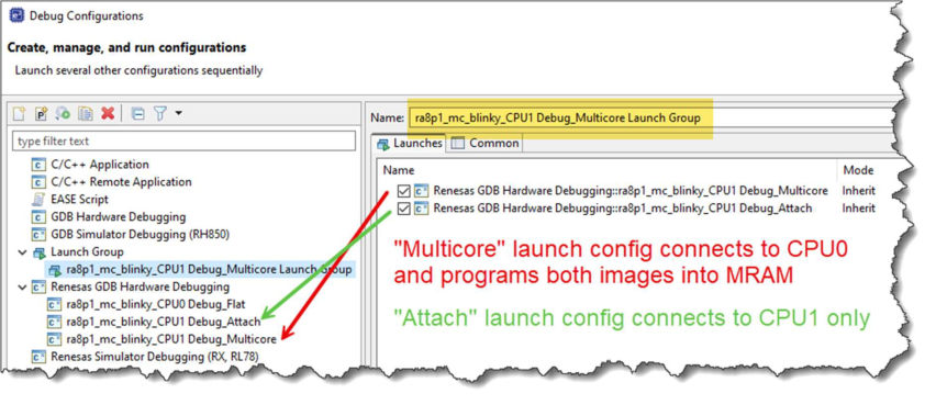
Note that the launch configuration generated inside the CPU0 project is generally not used when debugging the multicore application, as it simply connects to CPU0 and only programs the CPU0 image.
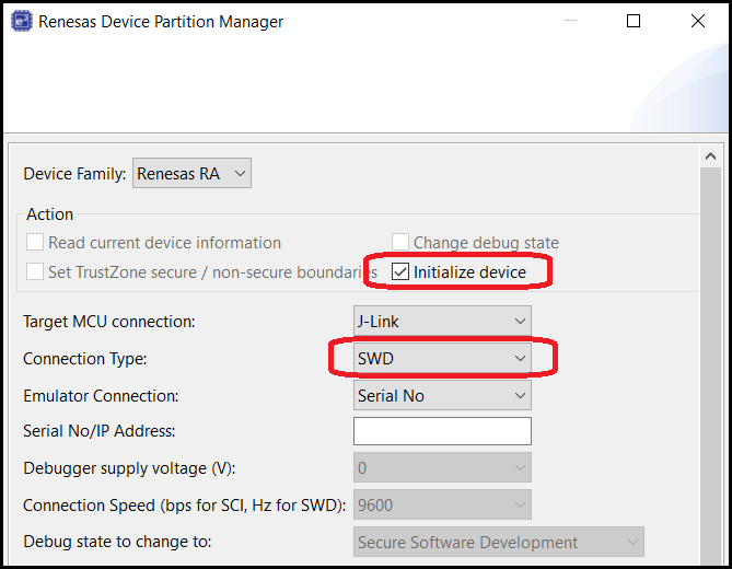
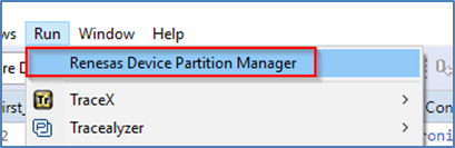
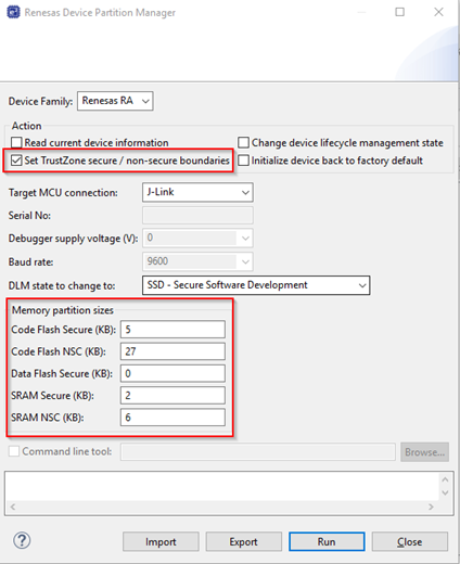
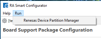
Important note: Currently the debug of multicore applications does not support the configuration of the TrustZone partition boundaries inside the MCU. Therefore before carrying out debug of a multicore application for the first time, it is necessary to use either RFP or RDPM to do an initialize operation of your MCU to ensure that the whole Code ROM (Flash/MRAM) area is marked as Secure. RDPM can be accessed from within e² studio by going to Run >> Renesas Debug Tools >> Renesas Device Partition Manager while a non-Solution project is selected. If this is not done, the download of your images and debug startup may not work correctly. This will be improved in a future release of FSP and e² studio.
The image below shows the RDPM settings to initialize an EK-RA8P1. Note that "Initialize device" is selected and the Connection Type was changed to "SWD". It is recommended to power cycle the board after using RDPM and before debugging.
The first time you start debugging your multicore application, you will need to open the Debug Configurations dialog:
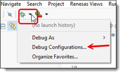
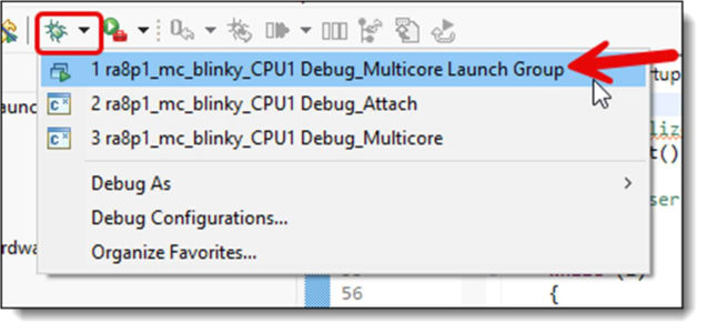
You will see the launch group that has been created. Select the Multicore Launch Group, then click the Debug button to start the debug session.
You should see the CPU0 project debug session start up and connect, followed by the CPU1 project. CPU1 will be shown in the Debug tree but will still be held in reset.
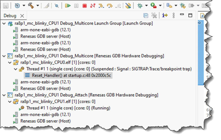
With the Reset_Handler() of the CPU0 elf file highlighted, if you now resume, CPU0 will start running. Once you pass main(), one of the LEDs on your board will begin to blink.
Once the call to R_BSP_SecondaryCoreStart() has been made from the CPU0 code, the CPU1 debug connection will also become fully active. At this point you can control CPU1 as you would CPU0.
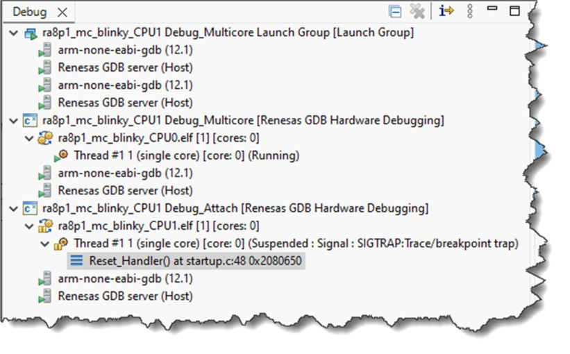
In the above screenshot, the Reset_Handler() of the CPU1 project is highlighted. Clicking Resume will start running code on CPU1. Once execution of main() on CPU1 has started, the 2nd LED on your board will also begin to blink.
Once connected to both cores, the currently active debug connection (as highlighted in the Debug view) is the one that will be controlled by the usual debug controls (step, resume, suspend, etc).
However it is possible to have these buttons control both debug connections in parallel, by selecting both connections at once in the Debug View (using the control key to multi-select):
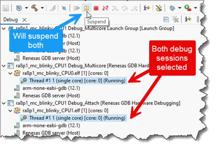
Note that the synchronization of operations here is being done at the software level within the GUI (cycling through each debug connection in turn, carrying out the requested operation). Although not fully lockstepped at the MCU hardware level, the functionality this provides is still useful in many circumstances.
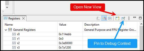
With regard to other views such as Registers, Memory, and Breakpoints, these will show the MCU state as seen by the currently selected core. However it is possible to pin each of these to a particular core, and also to clone the views so that you can have one pin to each core.
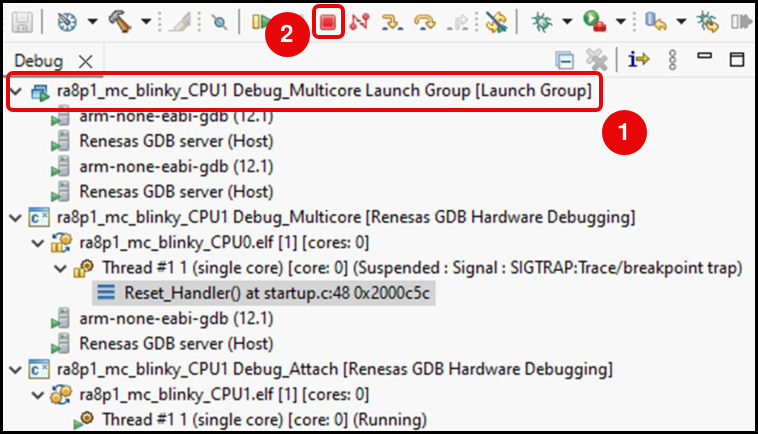
Once you have carried out your first multicore debug session, you can start further debug sessions simply using the appropriate Launch Group option which will then appear on the drop down menu:
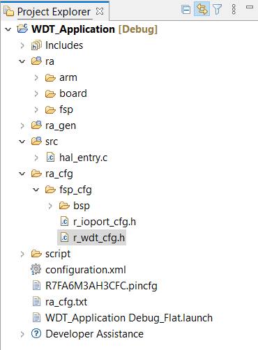
This tutorial illustrates the creation of a simple application that uses the Watchdog Timer module to monitor program operation. The tutorial shows each step in the development process and in particular identifies the auto-generated files and project structure created when using FSP and its GUI based configurator. The level of detail provided here is more than is normally needed during development but can be helpful in explaining how FSP works behind the scenes to simply your work.
This application makes use of the following FSP modules:
The Flexible Software Package (FSP) from Renesas provides a complete driver library for developing RA MCU applications. FSP provides Hardware Abstraction Layer (HAL) drivers, Board Support Package (BSP) drivers for the developer to use to create applications. FSP is integrated into Renesas e² studio based on eclipse providing build (editor, compiler and linker) and debug phases with an extended GNU Debug (GDB) interface.
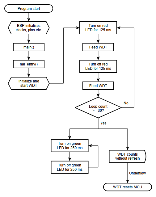
The flowchart for the WDT application is shown below.
The main sections of the WDT application are:
main() calls hal_entry(). The function hal_entry() is created by FSP with a placeholder for user code. The code for the WDT is added to this function.Start e² studio and choose a workspace folder in the Workspace Launcher. Configure a new RA MCU project as follows.
Select File > New > RA C/C++ Project. Then select the template for the project.
In the e² studio Project Configuration (RA Project) window enter a project name, for example, WDT_Application. In addition, select the toolchain. If you want to choose new locations for the project unselect Use default location. Click Next.
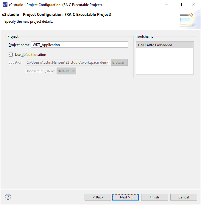
This application runs on the EK-RA6M3 board. So, for the Board select EK-RA6M3.
This will automatically populate the Device drop-down with the correct device used on this board. Select the Toolchain version. Select J-Link ARM as the Debugger. Click Next to configure the project.
The project template is now selected. As no RTOS is required select Bare Metal - Blinky.
Click Finish.
e² studio creates the project and opens the Project Explorer and Project Configuration Settings views with the Summary page showing a summary of the project configuration.
e² studio simplifies and accelerates the project configuration process by providing a GUI interface for selecting the options to configure the project.
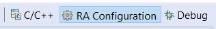
e² studio offers a selection of perspectives presenting different windows to the user depending on the operation in progress. The default perspectives are C/C++, FSP Configuration and Debug. The perspective can be changed by selecting a new one from the buttons at the top right.
The C/C++ perspective provides a layout selected for code editing. The FSP Configuration perspective provides elements for configuring a RA MCU project, and the Debug perspective provides a view suited for debugging.
configuration.xml file in the Project Explorer pane on the right side of e² studio.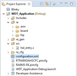
At the base of the Project Configuration view there are several tabs for configuring the project. A project may require changes to some or all of these tabs. The tabs are shown below.
The BSP tab allows the Board Support Package (BSP) options to be modified from their defaults. For this particular WDT project no changes are required. However, if you want to use the WDT in auto-start mode, you can configure the settings of the OFS0 (Option Function Select Register 0) register in the BSP tab. See the RA Hardware User's Manual for details on the WDT autostart mode.
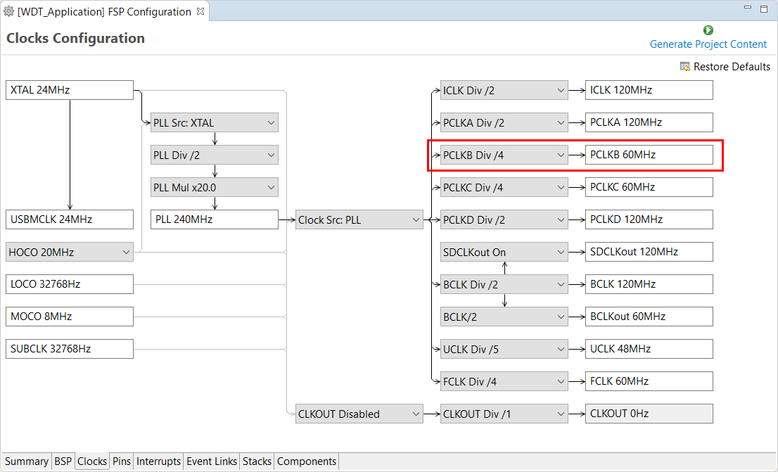
The Clocks tab presents a graphical view of the clock tree of the device. The drop-down boxes in the GUI enables configuration of the various clocks. The WDT uses PCLCKB. The default output frequency for this clock is 60 MHz. Ensure this clock is outputting this value.
The Interrupts tab is used to add new user events or interrupts. No new interrupts or events are needed by the application, so no edits in this tab are required.
The Event Links tab is used to configure events used by the Event Link Controller (ELC). This project doesn't use the ELC, so no edits in this tab are required.
The Pins tab provides a graphical tool for configuring the functionality of the pins of the device. For the WDT project no pin configuration is required. Although the project uses two LEDs connected to pins on the device, these pins are pre-configured as output GPIO pins by the BSP.
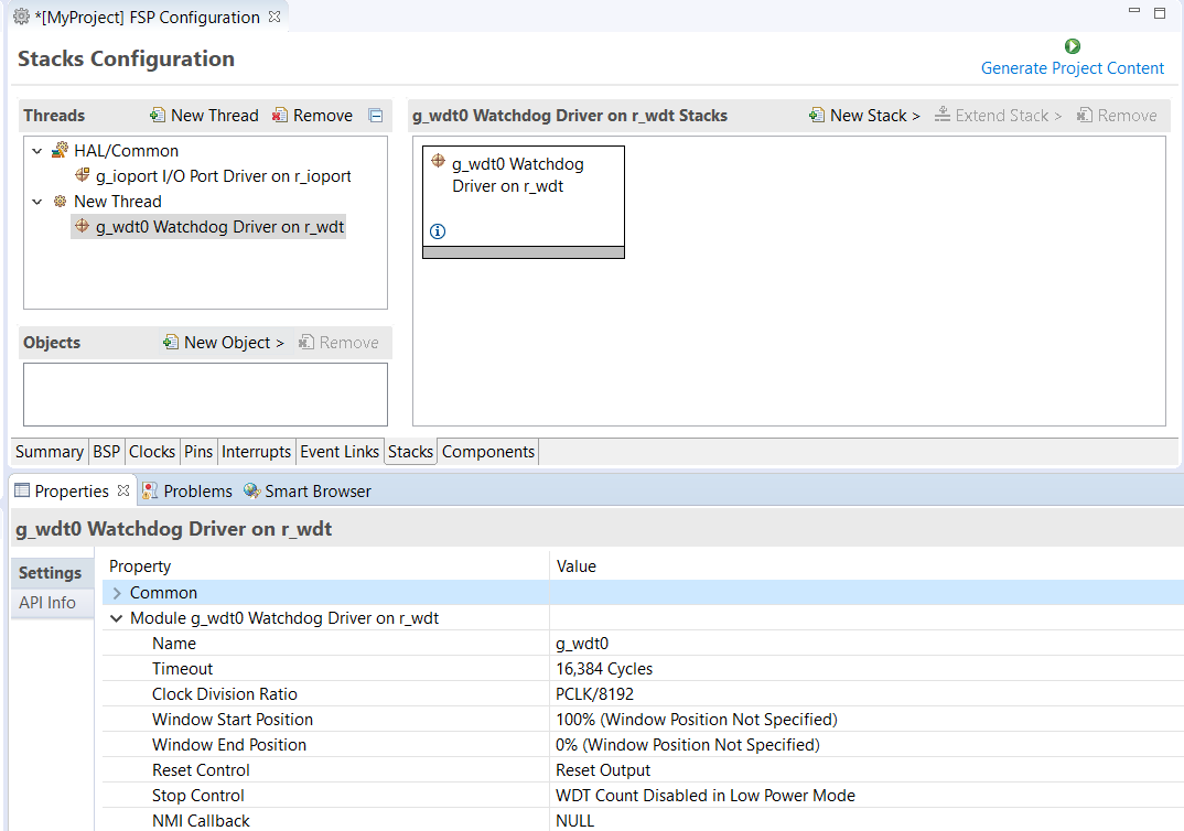
You can add any driver to the project using the Stacks tab. The HAL driver IO port pins are added automatically by e² studio when the project is configured. The WDT application uses no RTOS Resources, so you only need to add the HAL WDT driver.
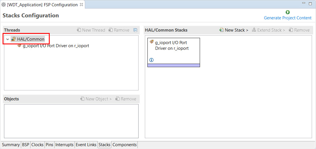
Click on the HAL/Common Panel in the Threads Window as indicated in the figure above.
The Stacks Panel becomes a HAL/Common Stacks panel and is populated with the modules preselected by e² studio.
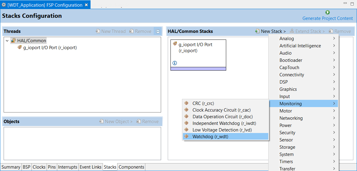
The selected HAL WDT driver is added to the HAL/Common Stacks Panel and the Property Window shows all configuration options for the selected module. The Property tab for the WDT should be visible at the bottom left of the screen. If it is not visible, check that the FSP Configuration perspective is selected.
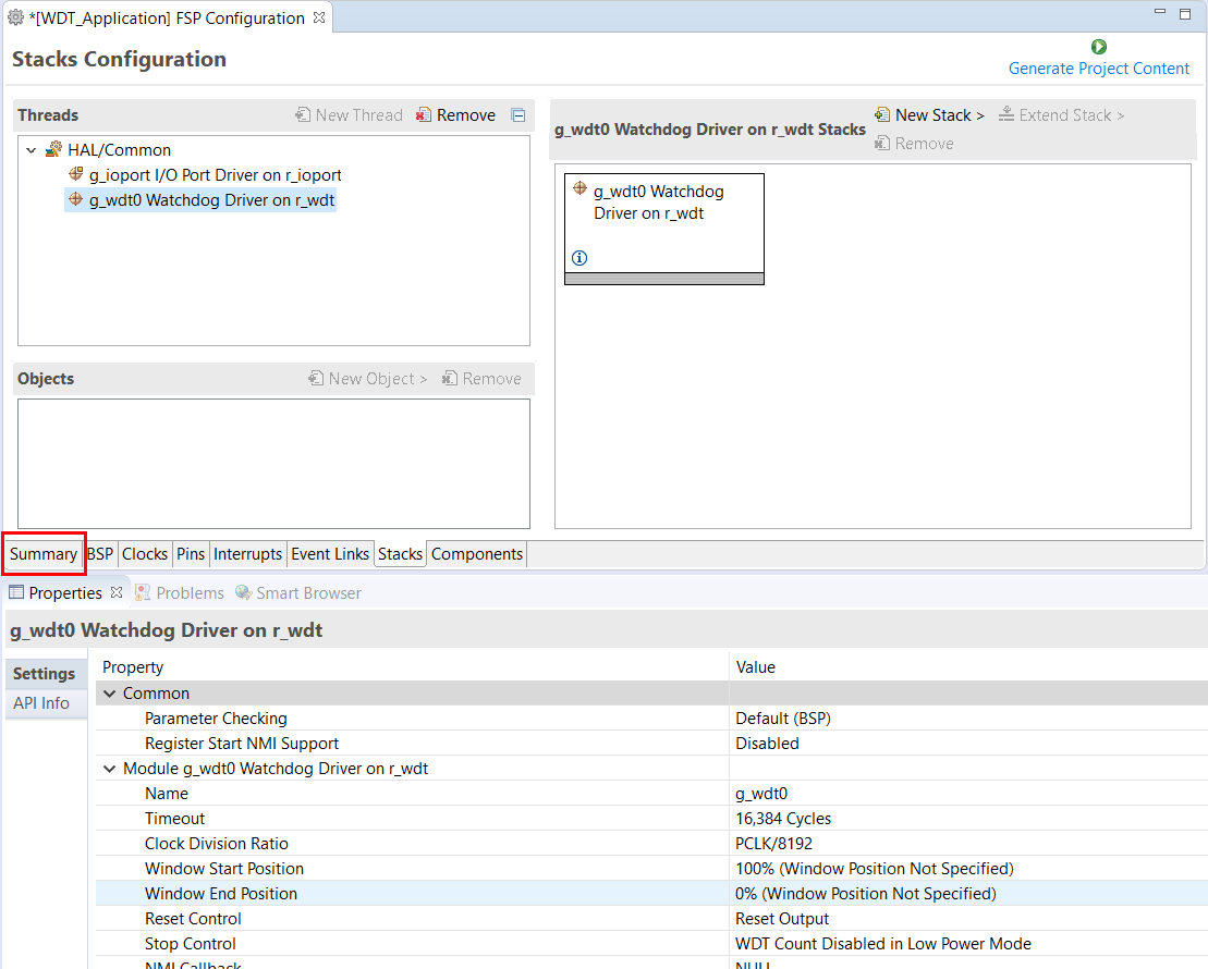
All parameters can be left with their default values.
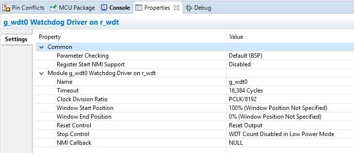
With PCLKB running at 60 MHz the WDT will reset the device 2.23 seconds after the last refresh.
WDT clock = 60 MHz / 8192 = 7.32 kHz
Cycle time = 1 / 7.324 kHz = 136.53 us
Timeout = 136.53 us x 16384 = 2.23 seconds
Save the Project Configuration file and click the Generate Project Content button in the top right corner of the Project Configuration pane.
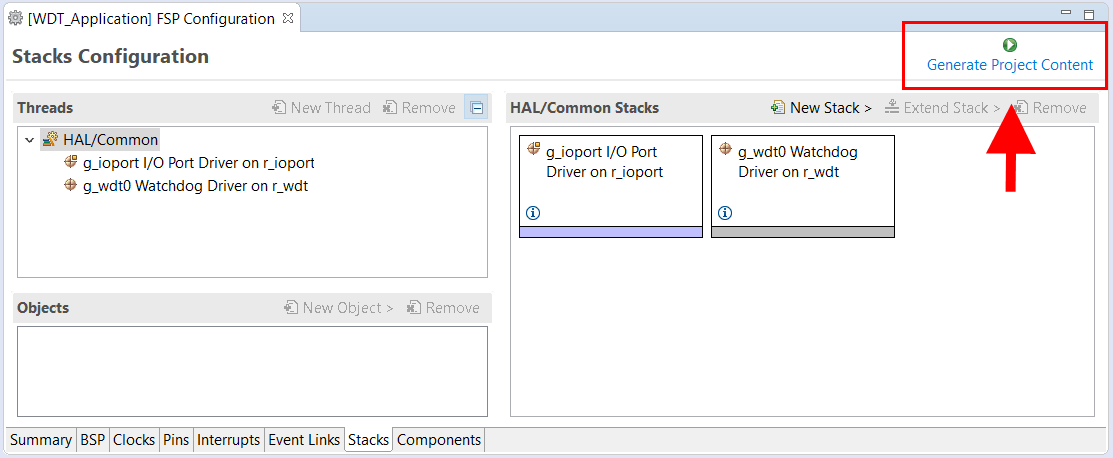
e² studio generates the project files.
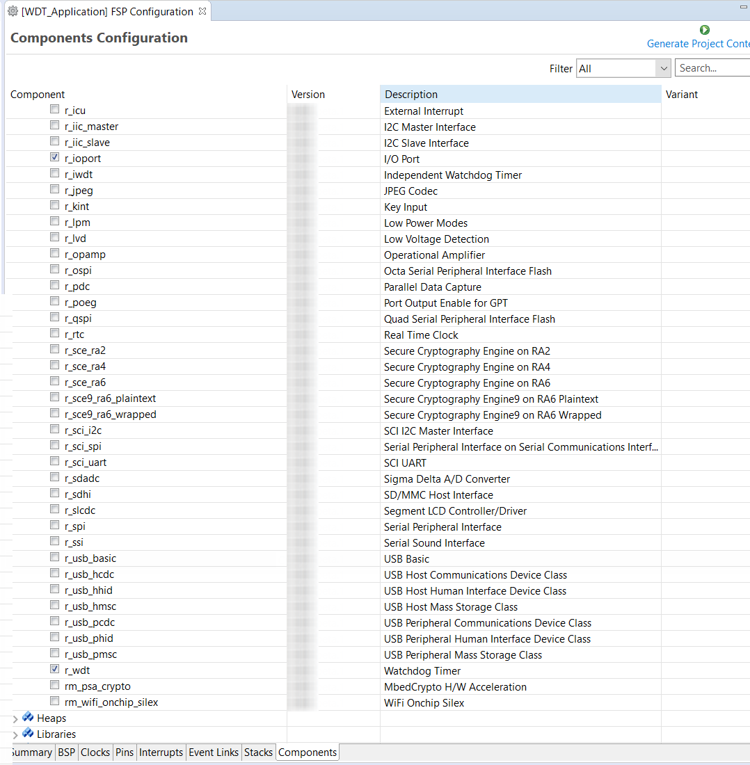
The components tab is included for reference to see which modules are included in the project. Modules are selected automatically in the Components view after they are added in the Stacks Tab.
For the WDT project ensure that the following modules are selected:
Clicking the Generate Project Content button performs the following tasks.
r_wdt folder and WDT driver contents created at:
ra/fsp/src
r_wdt_api.h created in:
ra/fsp/inc/api
r_wdt.h created in:
ra/fsp/inc/instances
The above files are the standard files for the WDT HAL module. They contain no specific project contents. They are the driver files for the WDT. Further information on the contents of these files can be found in the documentation for the WDT HAL module.
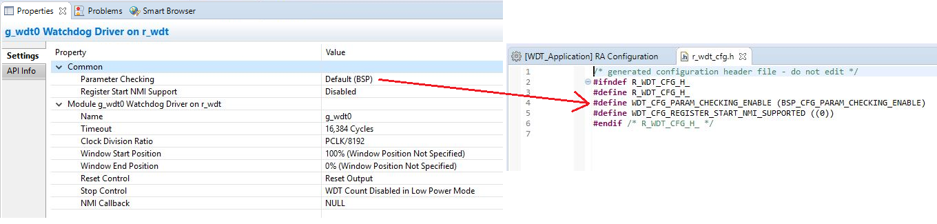
Configuration information for the WDT HAL module in the WDT project is found in:
ra_cfg/fsp_cfg/r_wdt_cfg.h
The above file's contents are based upon the Common settings in the g_wdt WATCHDOG Driver on WDT Properties pane.
The r_ioport folder is not created at ra/fsp/src as this module is required by the BSP and so already exists. It is included in the WDT project in order to include the correct header file in ra_gen/hal_data.c–see later in this document for further details. For the same reason the other IOPORT header files– ra/fsp/inc/api/r_ioport_api.handra/fsp/inc/instances/r_ioport.h–are not created as they already exist.
In addition to generating the HAL driver files for the WDT and IOPORT files e² studio also generates files containing configuration data for the WDT and a file where user code can safely be added. These files are shown below.
The contents of hal_data.h are shown below.
hal_data.h contains the header files required by the generated project. In addition this file includes external references to the g_wdt0 instance structure which contains pointers to the configuration, control, api structures used for WDT HAL driver.
The contents of hal_data.c are shown below.
hal_data.c contains g_wdt0_ctrl which is the control structure for this instance of the WDT HAL driver. This structure should not be initialized as this is done by the driver when it is opened.
The contents of g_wdt0_cfg are populated in this file using the Watchdog Driver on g_wdt0 pane in the Project Configuration Stacks tab. If the contents of this structure do not reflect the settings made in the IDE, ensure the Project Configuration settings are saved before clicking the Generate Project Content button.
Contains main() called by the BSP start-up code. main() calls hal_entry() which contains user developed code (see next file). Here are the contents of main.c.
This file contains the function hal_entry() called from main(). User developed code should be placed in this file and function.
For the WDT project edit the contents of this file to contain the code below. This code implements the flowchart in overview section of this document.
The WDT HAL driver API functions are defined in r_wdt.h. The WDT HAL driver is opened through the open API call using the instance structure defined in r_wdt_api.h:
The first passed parameter is the pointer to the control structure g_wdt0_ctrl instantiated in hal_data.c. The second parameter is the pointer to the configuration data g_wdto_cfg instantiated in the same hal_data.c file.
The WDT is started and refreshed through the API call:
Again the first (and only in this case) parameter passed to this API is the pointer to the control structure of this instance of the driver.
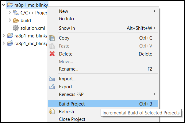
Build the project in e² studio by clicking Build > Build Project or by clicking the build icon. The project should build without errors.
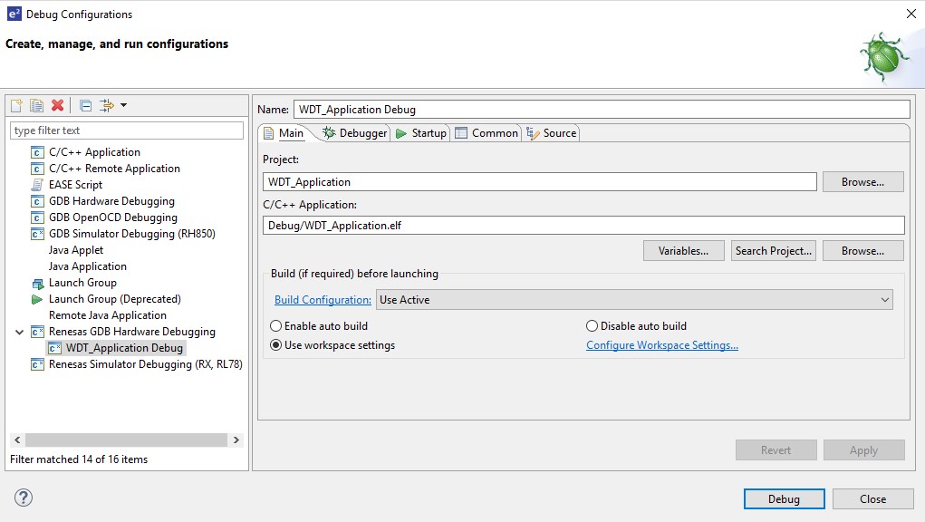
To debug the project
Under Renesas GDB Hardware Debugging select WDT_Application Debug as shown below.
Click the Debug button. Click Yes to the debug perspective if asked.
Reset_Handler() function.main() at the call to hal_entry().The red LED should start flashing. After 30 flashes the green LED will start flashing and the red LED will stop flashing.
While the green LED is flashing the WDT will underflow and reset the device resulting in the red LED to flash again as the sequence repeats.
This section will introduce the user to the tools supporting Arm® TrustZone® technology configuration for the RA Family of microcontrollers. It is intended to be read by development engineers implementing RA Arm TrustZone projects for the first time. It will introduce basic concepts followed by workflow and tooling functions designed to simplify and accelerate their first Arm TrustZone development. A background knowledge of e² studio and RA device hardware is expected.
RA Cortex®-M33 and Cortex®-M85 devices with Arm TrustZone security extension. As shown in the following table, most RA devices that include TrustZone support also support Device Lifecycle Management (DLM).
| MCU Groups with TrustZone and DLM | MCU Groups with TrustZone and no DLM | MCU Groups with TrustZone and Alternate DLM |
|---|---|---|
| RA4E1, RA4M2, RA4M3, RA6E1, RA6M4, RA6M5, RA6T2, RA8E1, RA8E2, RA8P1, RA8T2 | RA4E2, RA4T1, RA6E2, RA6T3 | RA8M1, RA8D1, RA8T1 |
The following section is supplied for reference only. For full details of TrustZone implementation, refer to Arm documentation (https://developer.arm.com/ip-products/security-ip/trustzone) and the MCU user manual.
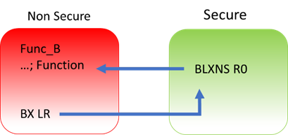
Arm TrustZone technology divides the MCU and therefore the application into Secure and Non-Secure partitions. Secure applications can access both Secure and Non-Secure memory and resources. Non-Secure code can access Non-Secure memory and resources as well as Secure resources through a set of so-called veneers located in the Non-Secure Callable (NSC) region. This ensures a single access point for Secure code when called from the Non-Secure partition. The MCU starts up in the Secure partition by default. The security state of the CPU can be either Secure or Non-Secure.
The MCU code flash, data flash, and SRAM are divided into Secure (S) and Non-Secure (NS) regions. Code flash and SRAM include a further region known as Non-Secure Callable (NSC). The method to set these memory security attributes depends on whether the device supports DLM:
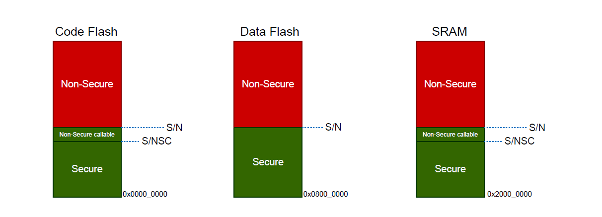
Note: All external memory accesses are considered to be Non-Secure.
Code Flash and SRAM can be divided into Secure, Non-Secure, and Non-Secure Callable. All secure memory accesses from the Non-Secure region MUST go through the Non-Secure Callable gateway and target a specific Secure Gateway (SG) assembler instruction. This forces access to Secure APIs at a fixed location and prevents calls to sub-functions and so on. Failing to target an SG instruction will generate a TrustZone exception.
TrustZone enabled compilers will manage generation of the NSC veneer automatically using CMSE extensions.
A new instruction SG (Secure Gateway) has been added to the Armv8-M architecture. This MUST be the destination instruction for any branch within the Non-Secure Callable region. If an attempt is made to branch to any other instruction from the Non-Secure partition, a TrustZone exception will be thrown.
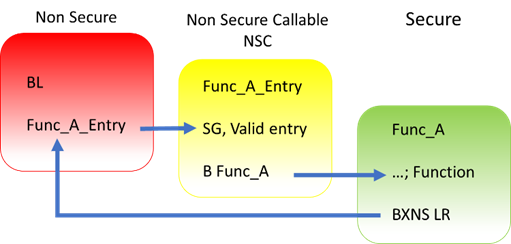
Secure code uses B(L)XNS instructions to make direct calls to Non-Secure functions. While this is certainly possible, it can create a security vulnerability in the application. It is also challenging for the Secure application to determine the address of the non-secure function during build phase. From the RA Tools and FSP point view, calling directly from Secure to Non-Secure via FSP API is not supported.
Preference is for the Secure code to initialise as necessary from reset, then pass control to the Non-Secure partition. It will manage any data transfers and so forth via FSP call-backs as security checks. For example, secure data can be copied to Non-Secure RAM.
Arm TrustZone MCU development normally consists of two projects within a workspace, Secure and Non-Secure. General project workflows are described in the following sections. The Renesas project generator also supports development with "Flat project" model with no Arm TrustZone awareness.
R_BSP_NonSecureEnter(); with while(1); in hal_entry.c.A flat project does not technically use Arm TrustZone as the developer has made a decision to place the entire application in Secure partition from restart.
Notes:
The workflow is as follows:
The RA project generators have been created to help users through setting up new TrustZone enabled projects. User will be prompted for project settings such as Project Type (Secure, Non-Secure, or Flat), compiler, RTOS and debugger. Care is needed when setting up a TrustZone project to ensure that the connection between Secure and Non-Secure partitions are managed correctly.
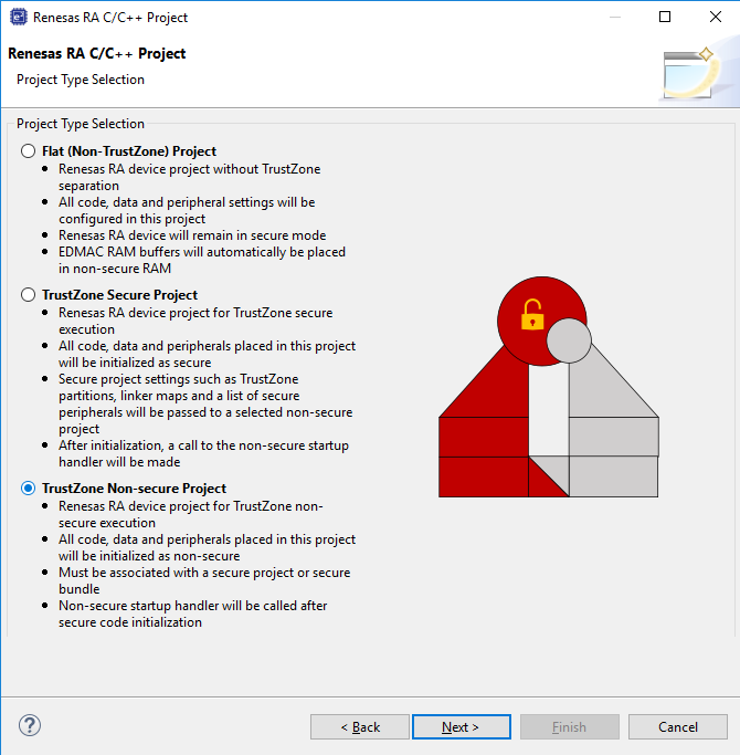
All code, data, and peripherals in this project will be configured as Secure using the device Peripheral Security Attribution (PSA) registers. Although it is very application specific, we recommend keeping the Secure project code as small as possible to reduce the attack surface. For example, secure key handling may be the only application code in the secure project.
Necessary values to set up the TrustZone memory partition (IDAU registers) will be automatically calculated after the project is built to ensure they match the code and data size, keeping the attack surface as small as possible.
Typically, ANSI C start up code (clearing of RAM, variable initialisation, etc) , clock, and secure peripheral initialisation will occur in this project.
At the end of the Secure code, a call will be made to R_BSP_NonSecureEnter(); to pass control to the Non-Secure partition.
Non-Secure Callable (NSC) "Guard" functions are added to the project and expose selected modules to Non-Secure projects. User can add application-specific access checks as needed in these functions.
Output of this project type will be an elf file that must be either pre-programmed (provisioned) into a device or referenced by a Non-Secure project (via Secure bundle *.SBD) to build a final image.
This project type will NOT typically be debugged in isolation and will normally require a Non-Secure project such as a call to a R_BSP_NonSecureEnter() to be made. This can be replaced with while(1); if needed.
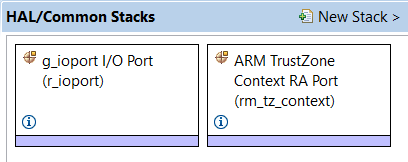
Although the RTOS kernel and user tasks will reside in the Non-Secure partition, the Secure partition needs to allocate stack space and so on. It is essential when starting a new RTOS project that the TrustZone Secure RTOS-Minimal template is selected. This will add the Arm TrustZone Context RA Port as below.
Each peripheral can be configured to be Secure or Non-Secure. Peripherals are divided into two types.
Type-1 peripherals have one security attribute. Access to all registers is controlled by one security attribute. The Type-1 peripheral security attribute is set in the PSARx (x = B to E) register by the secure application.
Type-2 peripherals have the security attribute for each register or for each bit. Access to each register or bit field is controlled according to these security attributes. The Type-2 peripheral security attribute is set in the Security Attribution register in each module by the Secure application. For more information about the Security Attribution register, see sections in the Appropriate MCU’s User’s Manual for each peripheral.
Table 1. Secure and Non-Secure Peripherals
| Type | Peripheral |
|---|---|
| Type 1 | SCI, SPI, USBFS, CAN, IIC, SCE9, DOC, SDHI, SSIE, CTSU, CRC, CAC, TSN, ADC12, DAC12, POEG, AGT, GPT, RTC, IWDT, WDT |
| Type 2 | System control (Resets, LVD, Clock Generation Circuit, Low Power Modes, Battery Backup Function), FLASH CACHE, SRAM controller, CPU CACHE, DMAC, DTC, ICU, MPU, BUS, Security setting, ELC, I/O ports |
| Always Non-Secure | CS Area Controller, QSPI, OSPI, ETHERC, EDMAC |
FSP will initialise the arbitration registers during Secure project BSP start up. User code may also be written to set or clear further arbitration. However care must be taken not to undermine FSP.
All code, data, and peripherals in this project will be configured as Non-Secure. This project type must be associated with a Secure project to enable access to secure code, peripherals, linker scripts and others.
All code, data, and peripherals are configured in a Secure single partition except for the EDMAC RAM buffers that will remain in the Non-Secure partition. Effectively, TrustZone is disabled.
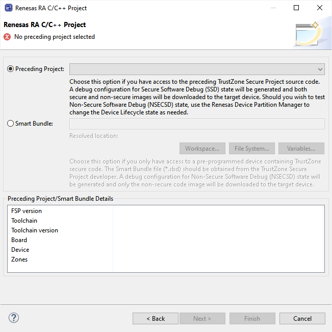
When starting a new Non-Secure Project, the user will be prompted for either a Secure Project or Secure Bundle. In each case, details of the linker settings, Non-Secure Callable functions, and Secure peripherals will be read to enable the Non-Secure project setup.
Should the Secure project or bundle be rebuilt, the Non-Secure editor will detect this and prompt user to regenerate the Non-Secure project configuration.
A Secure project must reside in the same Workspace as the Non-Secure project and will typically be used when a design engineer has access to both the Secure and Non-Secure project sources. This is sometimes known as "Combined model".
A Secure .elf file will be referenced and included in the debug configuration for download to the target device. The development engineer will have visibility of Secure and Non-Secure project source code and configuration.
A Secure Bundle will ONLY include linker memory ranges, symbol references, and details of locked Secure peripheral configuration settings but no access to Secure source code (API header files will be included as necessary).
The Secure bundle file (*.SBD) must be supplied to the Non-Secure developer by the Secure project developer.
The development engineer will typically not have access to the Secure project or .elf file which MUST be pre-programmed or provisioned into the target MCU.
For devices that support DLM, the DLM state of the target device should then be switched to NSECSD (see section 6.2) before the device is provided to the non-secure developer.
This is often referred to as "Split model" where a basic security set up is developed by a Secure team and then passed to the Non-Secure team in the same facility or at a third party. The Non-Secure team has no access to the Secure source code and cannot directly access Secure peripherals, data, or APIs.
After each project type has been selected, a suitable debug configuration will be generated.
Both Secure and Non-Secure .elf files will be downloaded.
A debug configuration called <project name>_SSD will be generated.
Only a Non-Secure elf will be downloaded. This configuration must be used with a pre-provisioned device (Secure project pre-programmed into MCU Flash).
A debug configuration called <project name>_NSECSD will be generated.
A single .elf file will be downloaded.
A debug configuration called <project name>_FLAT will be generated.
As mentioned, Secure code will be called immediately after device reset and run ANSI C start up, clock, interrupt vector table, and secure peripheral initialization before starting user code. All selected peripheral configuration settings will be automatically initialised as Secure.
Device clock settings are the possible exception in that they will be initialised in the Secure project (to enable faster start up from reset) but can be set as Secure or Non-Secure as user application may need to change settings during execution (for low-power mode and so on). The Secure and Non-Secure FSP BSPs can both change the clock settings.
However, clock settings can be locked as Secure should the developer choose to do so.
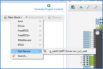
Some driver and middleware stacks in the Secure project may need to be accessed by the Non-Secure partition. To enable generation of NSC veneers, set "Non-Secure Callable" from the right-click context menu for the selected modules in the Configurator.
Note: It is only possible to "expose" top of stacks as NSC.
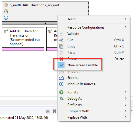
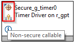
The top of the stack will be marked with a new icon and tool tip to signify NSC access.
Access to NSC drivers from a Non-Secure project is possible through the Guard APIs. FSP will automatically generate Guard functions for all the top of stack/driver APIs added to the project as Non-Secure Callable.
User can choose to add further levels of access control or delete guard function if they wish to only expose a limited range of APIs to a Non-Secure developer.
For example, an SCI channel may be opened and configured for a desired baud rate by the Secure developer, but only enable the Write API to the Non-Secure developer. In which case, all but g_uart0_write_guard() could be deleted. CTRL structures are not required as they will be added on the Secure side.
For example, the call from the Non-Secure partition would be as follows:
Configuration of the project can continue as for other RA devices, but certain resources will be locked if they have been previously set up as Secure.
The Non-Secure project will be called from the Secure project via R_BSP_NonSecureEnter();
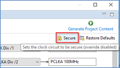
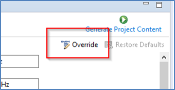
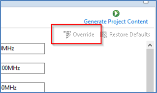
You may recall that clocks can be set as Secure or Non-Secure. If they are set as Secure, settings will only be available to view, and user will not be able to change them. The Override button will be greyed. This is useful to preserve CGC sync with secure project by not overriding unless necessary. If it is NOT set as Secure, user can choose to override the initial Secure settings
Drivers declared as NSC in a Secure project can be selected and added to Non-Secure project and will be decorated as before.
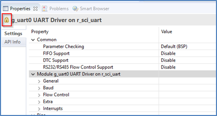
When a NSC Secure driver is added to a Non-Secure project, the configuration settings are locked and are available for information only. A padlock is added for indication.
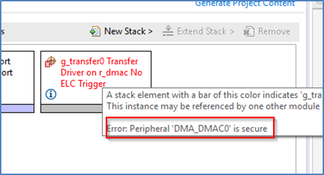
In a peripheral with multiple channels, for example, DMA, if a Non-Secure developer tries to select a channel that has already been defined as Secure, the following error message type will be displayed.
Renesas RA TrustZone-enabled devices include a set of registers known as Implementation Defined Attribution Unit (IDAU) that are used to set up partitions between Secure, Non-Secure Callable, and Non-Secure regions.
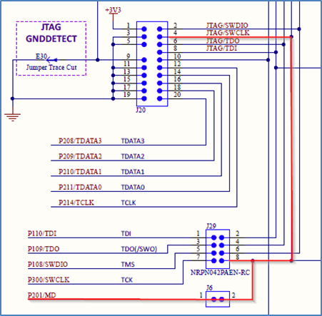
For devices that use DLM, the IDAU registers can only be programmed during MCU boot mode and NOT through the debug interfaces. Because of this, special debugger firmware has been developed to manage bringing the device up in SCI boot mode to set up the IDAU registers (automatically drives MD pin) and then switch back to debug mode as needed.
Note: Please be aware of the extra signal connection (MD pin) needed on the debug interface connector. The Renesas Evaluation Kit (EK) for your selected device is a good reference.
The e² studio build phase automatically extracts the IDAU partition register settings from the Secure .elf file and programs them into the device during debug connection, which can be observed in the console.
This is an important phase of TrustZone development as the Secure partitions should be set as small as possible to ensure that the security attack surface is as small as possible.
However, should the developer wish to make these partitions larger to accommodate, for example during field firmware updates, const or data arrays should be placed in the Secure project as needed.
It is also possible to manually set up the partition registers through the Renesas Device Partition Manager.
In e² studio, when manually setting partitions, make sure to disable setting partitions in the debug configuration to prevent the settings from being overridden when a debug session is launched.
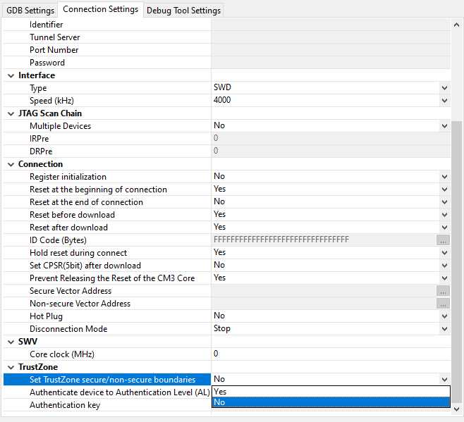
Example of MD mode pin connection to debugger connector (from EK schematic).
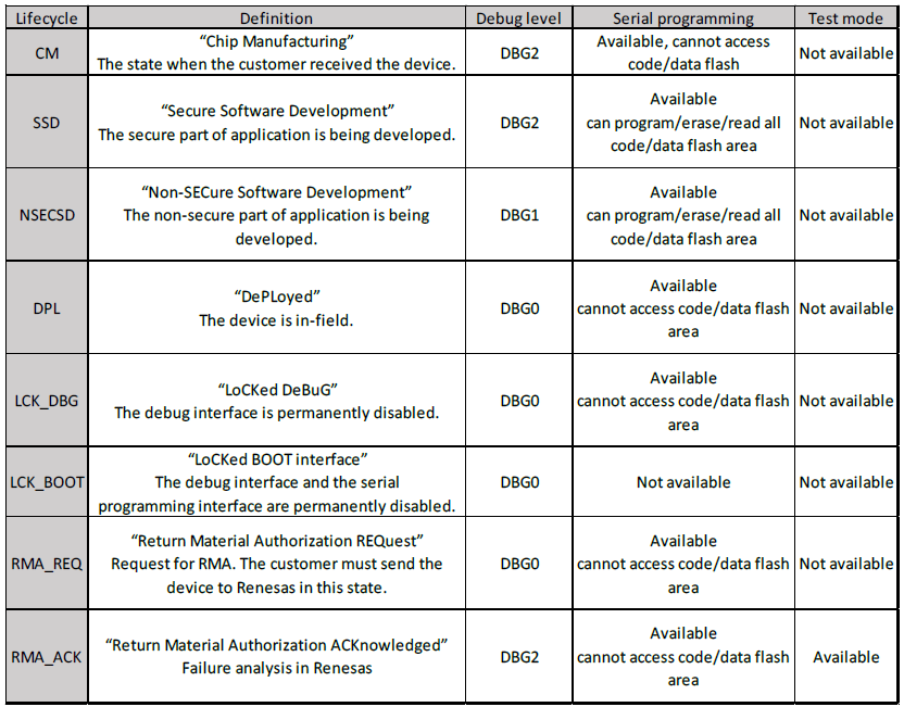
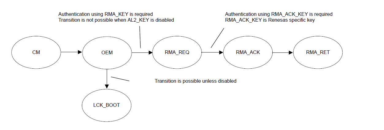
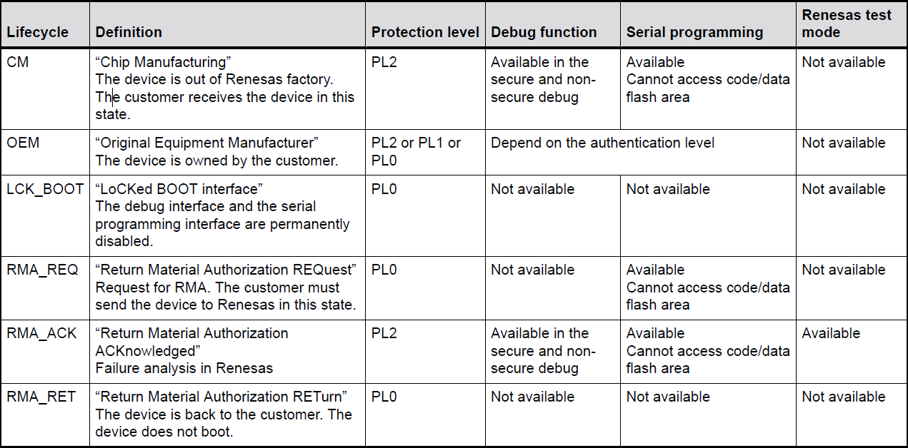
Device lifecycle defines the current phase of the device and controls the capabilities of the debug interface, the serial programming interface and Renesas test mode. The following illustration shows the lifecycle definitions and capability in each lifecycle.
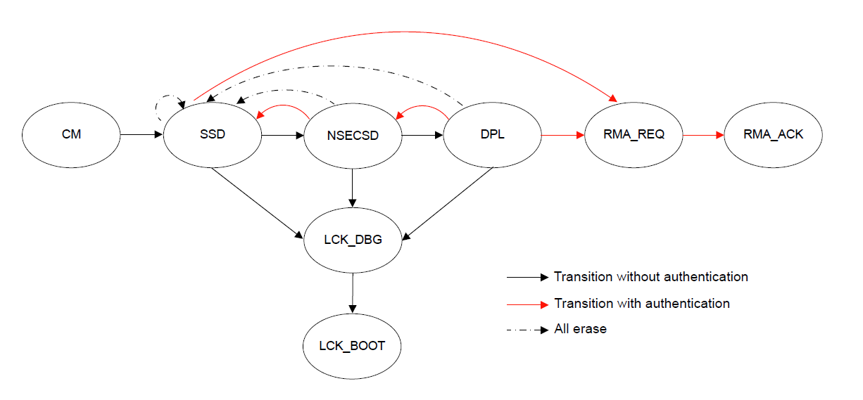
Note: All authentication key exchange and transitioning to LCK_DBG, LCK_BOOT, RMA_REQ is only managed by Renesas Flash Programmer (RFP) or other production programming tools, and NOT within e² studio.
There are three debug access levels. The debug access level changes according to the lifecycle state.
State transitions can be performed using the Renesas Flash Programmer (RFP, see section below) or using the Renesas Device Partition Manager (limited number of states possible). It is possible to secure transitions between states using authentication keys. For more information on DLM states and transitions (device specific), please refer to device user manual.
Some devices have an alternate implementation of Device Lifecycle Management (See Target Device). While the concept is the same, the DLM states are a little different. The following illustration shows the lifecycle definitions and capability in each lifecycle.
Note: All authentication key exchange and transitioning to LCK_BOOT, and RMA_REQ is only managed by Renesas Flash Programmer (RFP) or other production programming tools, and NOT within e² studio.
There are three authentication levels. The available authentication levels change according to the lifecycle state and determine the memory and resources that are accessible by the debugger.
State transitions can be performed using the Renesas Flash Programmer (RFP, see section below) or using the Renesas Device Partition Manager (limited number of states possible). It is possible to secure transitions between states using authentication keys. For more information on DLM states and transitions (device specific), please refer to device user manual.
In addition to having different DLM States, these devices also handle memory partitioning differently. Code Flash and Data Flash partitions are divided into secure and non-secure regions using SCI or USB boot mode commands. All other memory regions are set in IDAU and SAU registers in the secure application during the BSP startup procedure. All memory regions and peripherals that are configured as non-secure must be accessed using an aliased non-secure address. This non-secure address is calculated by setting bit 28 in the address.
For devices that do not have DLM, the IDAU registers are programmed by secure application code at startup. Devices without DLM do not support IDAU register programming using boot mode commands.
By default, devices supporting DLM will be in SSD mode and so allow access to Secure and Non-Secure partitions. In this mode both Secure and Non-Secure .elf files will be downloaded.
The current debugger status is displayed in the lower left corner and includes the DLM state (SSD or NSECSD) and current partition (Secure, Non-Secure, or Non-Secure Callable) when the debugger is stopped, for example.


Once the device is transitioned to NSECSD mode, only Non-Secure Flash, RAM and Peripherals can be accessed. In this mode, a Secure .elf must be pre-programmed (provisioned) into the device, and only a Non-Secure .elf file will be downloaded.
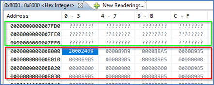
When in NSECSD mode access to Secure elements will be blocked and data displayed as ????????.
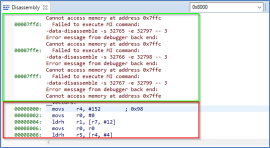
In NSECSD mode, it is not possible to set breakpoints on Secure code or data.
It is not possible to step into Secure code; the debugger will perform a step-over of any Secure function calls. Should the user press the Suspend button during execution, the debugger will stop at the next Non-Secure code access.
Assuming Secure memory region finishes at 32K (0x8000) in NSECSD debug mode (colour coding added for indication only), memory will be displayed as shown in the following figure.
Disassembly will be displayed as shown in the following figure.
Renesas E2, E2 Lite, and SEGGER J-Link are supported in e² studio for TrustZone projects.
Debugger Support for TrustZone Projects
| Feature | E2 Lite | E2 | J-Link | J-Link OB | ULINK | IAR I-jet |
|---|---|---|---|---|---|---|
| JTAG | Yes | Yes | Yes | No | Yes | Yes |
| SWD | Yes | Yes | Yes | Yes | Yes | Yes |
| ETB trace | Yes | Yes | Yes | Yes | Yes | Yes |
| ETM trace | No | Yes | Yes | No | Yes | Yes |
| TrustZone partition programming | Yes | Yes | Yes | Yes | No | Yes |
| Non secure debug | Yes | Yes | Yes | Yes | No | Yes |
| e² studio | Yes | Yes | Yes | Yes | No | No |
| IAR EW Arm | Yes | Yes | Yes | Yes | No | Yes |
| Keil MDK | Under consideration | Under consideration | Yes | Yes | Yes | No |
Third-party IDEs such as IAR Systems EWARM and Keil MDK (uVision) are supported by the RA Smart Configurator (RASC).
In general, RASC offers the same configurator functionality as e² studio documented above. Project generators are available to initialise workspaces in the target IDEs as well as setting up debug configurations and so forth. However, there are some limitations that need to be noted especially with regards to IDAU TrustZone partition register programming. See the specific RASC documentation for usage details.
Updated versions of Renesas Flash Programmer (RFP) are available to support setting of partitions, DLM state and Authentication keys.
RFP can be downloaded free of charge on the Renesas web site.
A new mode has been added to Program Flash Options as shown in the following graphics.
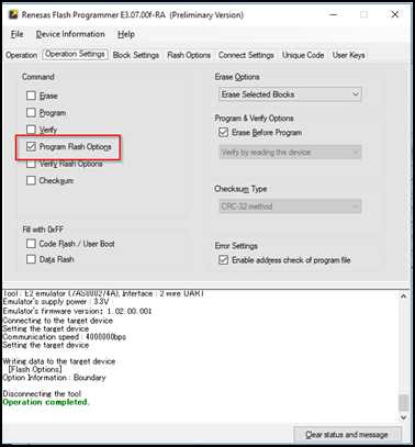
Options to set partition boundaries are shown in the following figure.
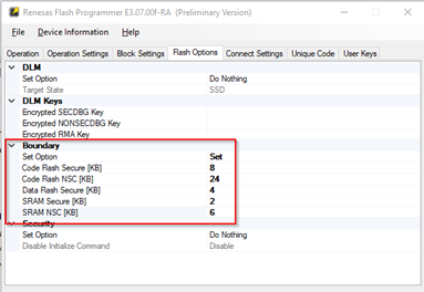
Options to set DLM state, Authentication keys, and Security settings are shown in the following figure.
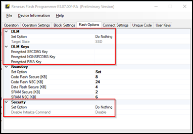
Great care is needed here as some DLM states can **permanently** turn off debug and boot mode on the devices. Equally programming a security access authentication key can lead to permanently locked devices if the key is lost.
IDAU
Implementation Defined Attribute Unit. Used to program TrustZone partitions.
NSECSD
Non-Secure Software Development mode
SSD
Secure Software Development mode
NSC
Non-Secure Callable. Special Secure memory region used for Veneer to allow access to Secure APIs from Non-Secure code.
Provisioned
Device with Secure code pre-programmed and DLM state set to NSECSD
Flat project
All code, data and peripherals are configured as secure with the exception of the EDMAC RAM buffer which are placed in Non-Secure RAM due to the configuration of the internal bus masters.
Veneer
Code that resides in Non-Secure Callable region
Combined model
Development engineer has access to both Secure and Non-Secure project and source code
Split model
Development Engineer has access to only the Non-Secure partition. No visibility of Secure source code. Secure code will be provisioned into device.
The Renesas RA Smart Configurator (RASC) is a desktop application designed to configure device hardware such as clock set up and pin assignment as well as initialization of FSP software components for a Renesas RA microcontroller project when using a 3rd-party IDE and toolchain.
The RA Smart Configurator can currently be used with
Projects can be configured and the project content generated in the same way as in e² studio. Please refer to Configuring a Project section for more details.
<keil_mdk_install_dir>\UV4. Select the menu item File > Import... and browse to the extracted .pack file.The following steps are required to create an RA project using Keil MDK, RASC and FSP:
Enter a project folder and project name.
Select the target device and IDE.
A new Keil MDK project file will be generated in the project path. Double click this file to open MDK and continue development as usual.
Once an initial project has been generated and configured, it is also possible to make changes using RASC as follows.
Set up the following links to RASC:
rasc.exe$Pconfiguration.xmlrasc.exe$P-application com.renesas.cdt.ddsc.dpm.ui.dpmapplication configuration.xml "$L%L"To reconfigure an existing project select Tools > RA Smart Configurator
To reconfigure the TrustZone partitions select Tools > Device Partition Manager
The project can be built by selecting the menu item Project > Build Target or tool bar item Rebuild or the keyboard shortcut F7.
Assembler, Compiler, Linker and Debugger settings can be changed in Options for Target dialog, which can be launched using the menu item Project > Options for Target, the tool bar item Options for Target or the keyboard shortcut Alt+F7.
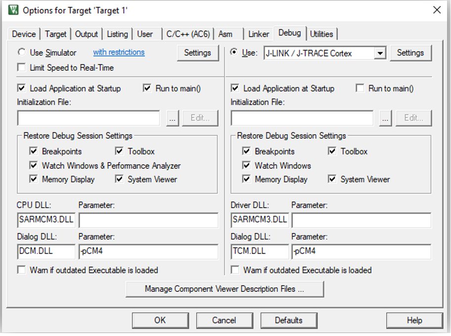
RASC will set up the uVision project to debug the selected device using J-Link or J-Link OB debugger by default.
A Debug session can be started or stopped by selecting the menu item Debug > Start/Stop Debug Session or keyboard shortcut CTRL+F5. When debugging for the first time, J-Link firmware update may be needed if requested by the tool.
Refer to the documentation from Keil to get more information on the debug features in uVision. Note that not all features supported by uVision debugger are implemented in the J-Link interface. Consult SEGGER J-Link documentation for more information.
For TrustZone enabled devices, the user will need to manually set up the memory partitions using the "Renesas Device Partition Manager" from inside RASC before downloading.
IAR Systems Embedded Workbench for Arm (EWARM) includes support for Renesas RA devices. These can be set up as bare metal designs within EWARM. However, most RA developers will want to integrate RA FSP drivers and middleware into their designs. RASC will facilitate this.
RASC generates a "Project Connection" file that can be loaded directly into EWARM to update project files.
The following steps are required to create an RA project using IAR EWARM, RASC and FSP:
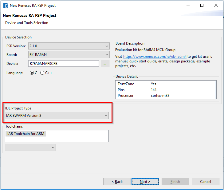
Enter a project folder and project name.
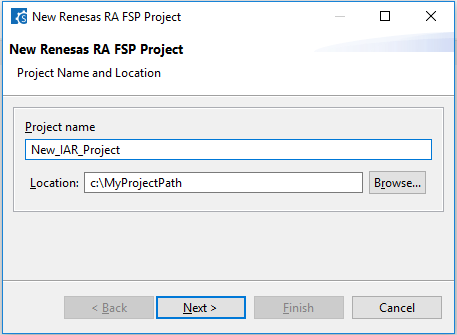
Select the target device and IDE.
rasc.exe in the installed RASCconfiguration.xml$PROJ_DIR$rasc.exe in the installed RASCapplication com.renesas.cdt.ddsc.dpm.ui.dpmapplication configuration.xml "$TARGET_PATH$"$PROJ_DIR$buildinfo.ipcf and click Open. The project can now build in EWARM.When starting a TrustZone enabled debug session Partition sizes are checked automatically.